
Device for detecting and comparing performance of filters as well as detection method

A detection device and filter technology, which is applied in the direction of measuring devices, scientific instruments, suspension and porous material analysis, etc., can solve the problems of high cost, long detection cycle, uneven quality, etc., and achieve low cost and simple structure Effect

Active Publication Date: 2015-07-22
SHANDONG UNIV +2
View PDF6 Cites 6 Cited by
  • Summary
  • Abstract
  • Description
  • Claims
  • Application Information

AI Technical Summary

Problems solved by technology

At present, there are many types of filters on the market, and the quality is uneven. Each manufacturer advertises that their filters have remarkable effects, but some do not follow the actual situation, exaggerate and mislead consumers.
Even if some manufacturers can come up with test reports, consumers are not sure whether the test reports are of the variety, batch, etc., and cannot visually observe the effect
[0003] At present, the cost of various filter testing equipment is high, and some manufacturers do not purchase it out of cost considerations. They can only go to special testing institutions for testing. The testing cost is high and the testing cycle is long.
[0004] Moreover, the filtration effect of the current test mainly uses several gases formulated by the standard, and it is not possible to filter and detect the specified gas according to the actual use needs.

Method used


Image

  • Device for detecting and comparing performance of filters as well as detection method
  • Device for detecting and comparing performance of filters as well as detection method
  • Device for detecting and comparing performance of filters as well as detection method

Examples


Embodiment 1

[0044] Take the need to detect the filtering effect of hydrogen sulfide gas treated by the filter as an example.

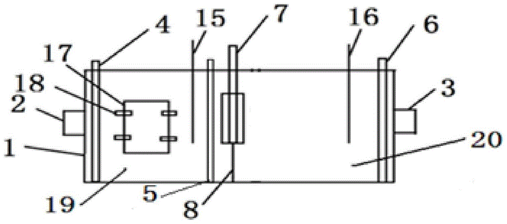
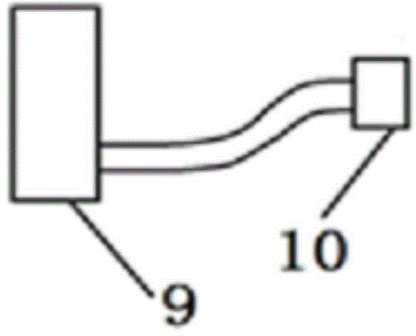
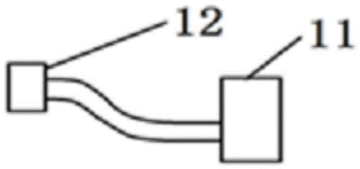
[0045] Connect the devices involved in this application, the hydrogen sulfide gas cylinder is used as the detection source generating device 9, the hydrogen sulfide concentration detector is used as the pre-filtration detector 15 and the post-filtration detector 16, the first sealing plate 4 is opened, and the second sealing plate 5 is dropped , open the gas cylinder, and when the hydrogen sulfide gas fills the detection atmosphere chamber 19 and reaches the specified concentration, close the gas cylinder and drop the first sealing plate 4 . Connect the vacuum pump interface 12 to the detection source discharge port 3, and use the vacuum pump 11 to vacuumize. When the vacuum degree reaches 0.5MPa, drop the third sealing plate 6, remove the vacuum pump 11, and connect the detection source discharge port 3 to the detection source processing device interface. 14. Put...

Embodiment 2

[0047] Take the need to detect and compare the dust filtration effects of two filters as an example.

[0048] Connect the two devices of the present application, the dust raising device is used as the detection source generating device 9, the portable dust detector is used as the pre-filtration detector 15 and the post-filtration detector 16, the first sealing plate 4 is opened, and the second sealing plate 5 is dropped. Turn on the dust raising device, and when the dust fills the detection atmosphere chamber 19 and reaches a specified concentration, turn off the dust raising device and drop the first sealing plate 4 . Utilize the vacuum pump 11 to vacuumize, and when the degree of vacuum reaches 1 MPa, drop the third sealing plate 6, take off the vacuuming device, connect the detection source discharge port 3 to the detection source processing device interface 14, and put water into the detection source processing device interface 14. . Everything is ready, raise the second ...

Embodiment 3

[0050] For example, it is only necessary to compare the dust filtration effects of the two filters without specific test data.

[0051] Connect the two devices of the present application, the dust raising device is used as the detection source generating device 9, without installing the pre-filtering detector 15 and the post-filtering detector 16, the first sealing plate 4 is opened, the second sealing plate falls, and the dust raising device is opened. When the dust is full of the detection atmosphere chamber 19 and the colors of the two filter performance detection devices 1 are consistent, close the dust raising device and drop the first sealing plate. Use the vacuum pump 11 to vacuumize. When the vacuum degree reaches 1MPa, drop the third sealing plate, remove the vacuum device, connect the detection source discharge port 3 to the detection source processing device interface 14, and put water into the detection source processing device 13. Everything is ready, raise the se...


PUM


Abstract

The invention relates to a device for detecting and comparing the performance of filters as well as a detection method. The device comprises a filter performance detecting device, a detecting source generating device used for generating a detecting source, a detecting source processing device used for detecting post-processing detecting source, and a vacuum-pumping device used for vacuumizing before detection, wherein the filter performance detecting device comprises a sealing outer housing, a detection atmosphere chamber and a vacuum chamber; a detecting filter device used for mounting of a detected filter is arranged in the vacuum chamber; the detecting source generating device is communicated with detecting atmosphere chamber through an detecting source inlet; the detecting source processing device and the vacuum-pumping device are communicated with the vacuum chamber through detecting source discharge outlets respectively; a pre-filtration detecting instrument and a post-filtration detecting instrument are arranged at the tops of the detecting atmosphere chamber and the vacuum chamber respectively. The sealing outer housing is transparent, so that the filter effect of each filter can be observed relatively intuitively, and the filter effects of different filters can be observed relatively intuitively.

Description

technical field [0001] The invention relates to the field of filter detection, in particular to a device and a detection method for detecting and comparing the performance of filters. technical background [0002] With the increasingly serious environmental pollution, various filters have emerged as the times require, including breathing filters, air filters, water filters and so on. At present, there are many types of filters on the market, and the quality is uneven. Each manufacturer advertises that their filters have remarkable effects, but some do not follow the actual situation, exaggerate and mislead consumers. Even if some manufacturers can come up with test reports, consumers cannot be sure whether the test reports are of the variety, batch, etc., and cannot directly observe the effect. [0003] At present, the cost of various filter testing equipment is high, and some manufacturers do not purchase them out of cost considerations. They can only go to special testing...

Claims


Application Information

Patent Timeline
Patent Type & Authority Applications(China)
IPC IPC(8): G01N15/08
Inventor 朱波乔琨关勇虞军伟
Owner SHANDONG UNIV
Learn More