Multichannel 2x2 photoswitch

An optical switch and multi-channel technology, which is applied in the direction of light guide, optics, optical components, etc., can solve the problems that the optical crystal coating layer is easily oxidized or polluted, affects the working life of the optical switch, and changes in the insertion loss of the optical path, and achieves low production costs. , good sealing performance and low insertion loss

Active Publication Date: 2015-07-22
NO 34 RES INST OF CHINA ELECTRONICS TECH GRP
View PDF10 Cites 0 Cited by
  • Summary
  • Abstract
  • Description
  • Claims
  • Application Information

AI Technical Summary

Problems solved by technology

[0004] The current 1×2 and 2×2 mechanical optical switches mainly use viscose technology, which is inconvenient to install and adjust, and has poor sealing performance. Therefore, the optical crystal coating layer is easily oxidized or polluted, which not only affects the work of the optical switch Life span also limits the operating temperature of the optical switch to -20°C ~ +70°C, and the change in the insertion loss of the optical path exceeds 0.2dB

Method used


Image

  • Multichannel 2x2 photoswitch
  • Multichannel 2x2 photoswitch
  • Multichannel 2x2 photoswitch

Examples


Embodiment Construction

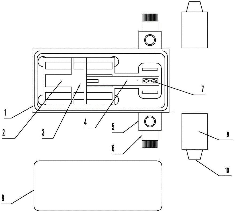
[0019] The embodiment of an 8-channel 2×2 optical switch will be further described below in conjunction with the accompanying drawings.

[0020] Such as figure 1 As shown, in the embodiment of the 8-channel 2X2 optical switch, the bottom box 1 has a cuboid inner cavity, the relay 3 is embedded in the bottom of the inner cavity of the bottom box 1, the bottom of the bottom box 1 has pin holes, and the pins of the relay 3 are from the bottom The pin hole of box 1 sticks out, connect the drive wire. There is respectively a plug hole on the two opposite sides of the bottom box 1, and the plug holes on each side are respectively fixedly connected to the plug pipe 5 outside the side, and the centerlines of the plug pipe 5 on the two sides are in a straight line, and the The straight line is perpendicular to the side of the bottom box 1 where the plug pipe 5 is installed. Two 8-core optical collimators 6 are respectively inserted into the plug tube 5 on one side. After the optical ...


PUM


Abstract

The invention relates to a multichannel 2x2 photoswitch. A relay is inlaid in a bottom box; plug holes are respectively formed in two opposite side surfaces of the bottom box; an N-core optical collimator is fixedly arranged in each plug hole; N can be 4, 8, 12 or 16; and the central axes of the collimators on the two sides of the bottom box are superposed to each other. The rear end of a swinging plate hinged to the relay is positioned above a coil; a cantilever arm is fixed at the front end of the swinging plate; and n=N/4 prisms are fixedly arranged at the front end of the cantilever arm. When the multichannel 2x2 photoswitch is in an initial state, the prisms are positioned below light paths of the collimators, and light paths of the collimators at an inputting end and an outputting end are communicated to each other directly. When the relay is electrified, the swinging plate is raised, the prisms on the cantilever arms are placed in the light paths of the optical collimators, outputting light of the optical collimator of the inputting end is refracted and reflected by the prisms and then enters another light path of the outputting end, and each prism can switch 4 light paths. Each optical collimator is inserted in a plug tube fixedly connected to the corresponding plug hole and is fixed, and a plug sleeve sleeves each optical collimator so as to protect the optical collimator. The bottom box is closed by a cover plate, various seams are sealed in a metalized manner, and the bottom box is filled with nitrogen. The multichannel 2x2 photoswitch is simple in structure, low in loss, convenient to adjust, high in precision and long in service life.

Description

technical field [0001] The invention relates to the technical field of optoelectronic devices, in particular to a multi-channel 2X2 optical switch. Background technique [0002] An optical switch is an optical passive device that realizes the on-off of optical signals and changes in the optical path. At present, the optical switch technology is relatively mature, and various products are widely used in optical path switching, system monitoring, optical path protection switching test, optical fiber sensing system, optical device testing, optical add / drop multiplexing (OADM), time division multiplexing (TDM) , Wavelength Division Multiplexing (WDM) and other occasions. Optical switches have broad market prospects and are one of the most promising optical passive devices. [0003] Most of the existing optical switches are basically mechanical optical switches with a relay and motor structure, that is, two optical fiber collimators are used to align with each other to realize ...

Claims


Application Information

Patent Timeline
Patent Type & Authority Applications(China)
IPC IPC(8): G02B6/35
CPCG02B6/3546
Inventor 钟昌锦张通勇刘武余志强黄涌周剑超林之华
Owner NO 34 RES INST OF CHINA ELECTRONICS TECH GRP
Why Eureka
Try Eureka