
Protection circuit, drive control system and control method of drive control system

A drive control and protection circuit technology, applied in control systems, emergency protection circuit devices, DC motor speed/torque control, etc., can solve problems such as short circuit, short circuit between motor wiring harness and power supply, short circuit between power supply and ground, etc.

Active Publication Date: 2015-07-22
HELLA SHANGHAI ELECTRONICS
View PDF5 Cites 3 Cited by
  • Summary
  • Abstract
  • Description
  • Claims
  • Application Information

AI Technical Summary

Problems solved by technology

[0004] 1. Relay failure: refer to image 3 and Figure 4 , the bonding of the relay causes the power to be turned on for a long time; the deformation of the shrapnel of the relay causes a direct short circuit between the power supply and the ground
[0005] 2. Harness failure: refer to Figure 5 and Image 6 , the wire harness is worn out and short-circuited with the body ground, which leads to a direct short-circuit between the power supply and the ground when the relay operates; some extreme conditions lead to a direct short-circuit between the motor wire harness and the power supply
[0007] Since the control module stops working when the motor is locked, it is impossible to diagnose this fault and close the relay, so such problems in the prior art can only be solved by replacing the fuse or the control module

Method used


Image

  • Protection circuit, drive control system and control method of drive control system
  • Protection circuit, drive control system and control method of drive control system
  • Protection circuit, drive control system and control method of drive control system

Examples


Embodiment Construction

[0045] The advantages of the present invention will be further elaborated below in conjunction with the accompanying drawings and specific embodiments.

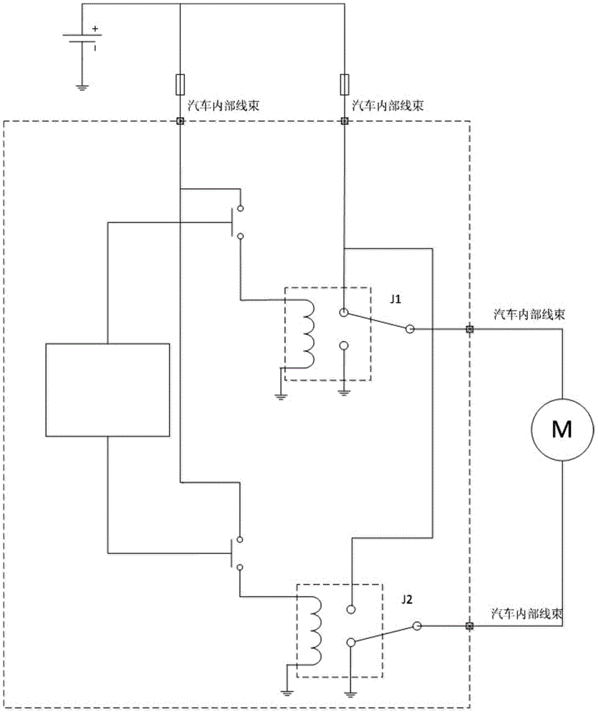
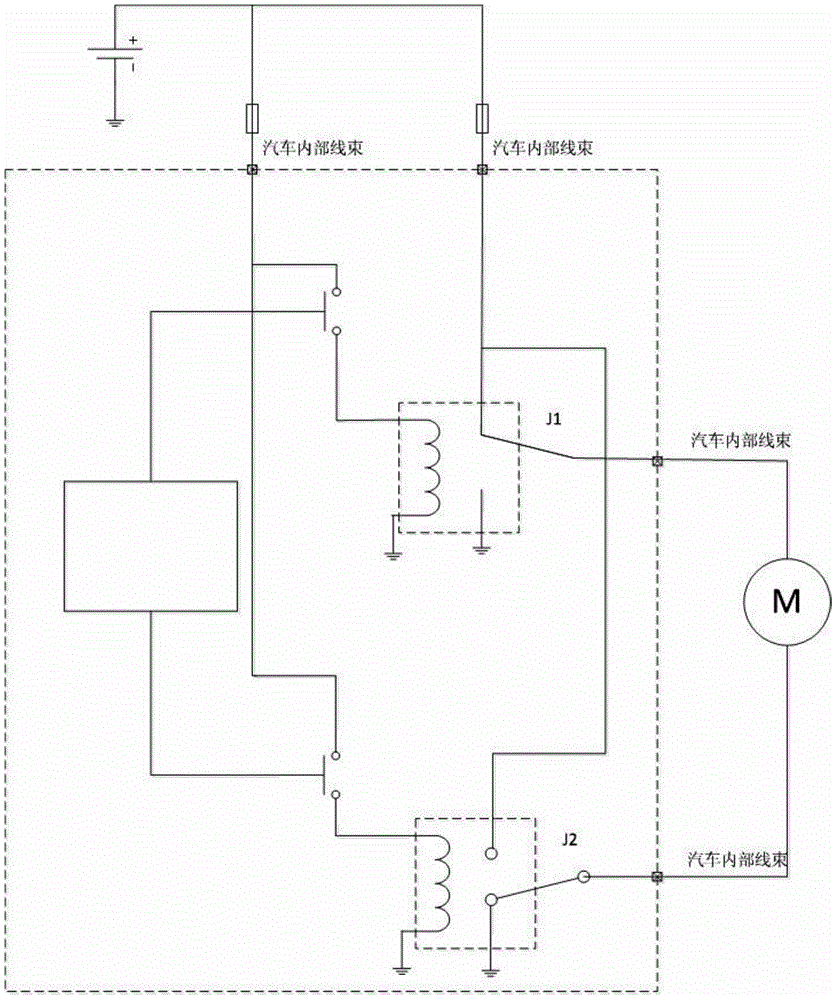
[0046] refer to Figure 8, is a schematic diagram of a drive control system with a protection circuit in the present invention. In the drive control system, the protection circuit includes a single-chip microcomputer and a mos tube module assembly, wherein the mos tube module assembly includes a mos tube and a mos tube drive module, the two are electrically connected to each other, and the mos tube drive module drives the mos tube to open or off. The single-chip microcomputer is electrically connected with the mos tube drive module, and outputs control instructions to it, and the control mode of driving the mos tube on or off by the mos tube drive module is driven by the single-chip microcomputer. The mos tube module assembly can detect the voltage at both ends of itself, and send the detected voltage value of the mos tube ...


PUM


Abstract

The invention discloses a protection circuit. The protection circuit comprises a single-chip microcomputer and an mos tube module assembly, and the mos tube module assembly comprises an mos tube and an mos tube driving module electrically connected with the mos. The single-chip microcomputer is electrically connected with the mos tube driving module to output a control instruction; the mos tube module assembly detects the voltage of itself, and sends the voltage to the single-chip microcomputer for sampling; and the single-chip microcomputer determines the voltage, and then outputs the control instruction to the mos driving module to control ON / OFF of the mos tube, thereby protecting circuit components in serial connection with the mos tube module assembly. Thus, a relay can be automatically disconnected from the ground even if a motor loop is shorted, and a fuse and a control module are prevented from burnout if a motor wire harness makes contact with or is wound with a battery wire harness.

Description

technical field [0001] The invention relates to the field of automobile internal circuits, in particular to a protection circuit, a drive control system and a control method thereof. Background technique [0002] With the increasing requirements of users for the intelligence, automation and comfort of automobiles, automatic functions such as automatic lifting of windows, automatic folding of rearview mirrors, automatic retracting of fuel tank caps, etc. are widely used in modern automobiles, and these intelligent The realization of the functions requires the DC motor to drive the mechanical structure to realize. refer to figure 1 , which is a schematic diagram of the control and connection of the DC motor in the prior art. At present, the running switch of the DC motor is realized through the operation of the control module, and the control module is realized by the single-chip microcomputer in the module to control the relay switch. DC The motor is connected to the relay ...

Claims


Application Information

Patent Timeline
Patent Type & Authority Applications(China)
IPC IPC(8): H02H3/087H02H7/08H02P7/00
Inventor 任磊丁大胜金红宾周彤
Owner HELLA SHANGHAI ELECTRONICS
Learn More