Supercharge Your Innovation With Domain-Expert AI Agents!

Water-cooled permanent magnet energy-saving speed regulating motor

A speed-regulating motor and water-cooling technology, applied to electrical components, electromechanical devices, electric components, etc., can solve problems such as high maintenance costs, complicated speed-regulating technology, and poor reliability

Inactive Publication Date: 2017-06-27
南京银茂永磁节能科技有限公司
View PDF6 Cites 0 Cited by
  • Summary
  • Abstract
  • Description
  • Claims
  • Application Information

AI Technical Summary

Problems solved by technology

[0004] The purpose of this technology is to provide a water-cooled permanent magnet energy-saving speed-regulating motor to overcome the shortcomings of the existing motor speed-regulating technology, such as complexity, poor reliability, and high maintenance costs.

Method used


Image

  • Water-cooled permanent magnet energy-saving speed regulating motor
  • Water-cooled permanent magnet energy-saving speed regulating motor
  • Water-cooled permanent magnet energy-saving speed regulating motor

Examples


Embodiment Construction

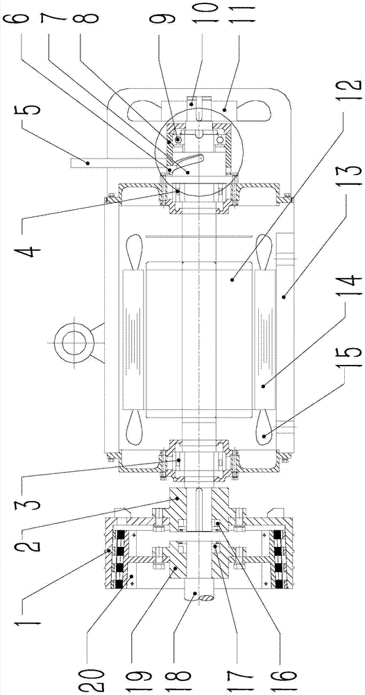
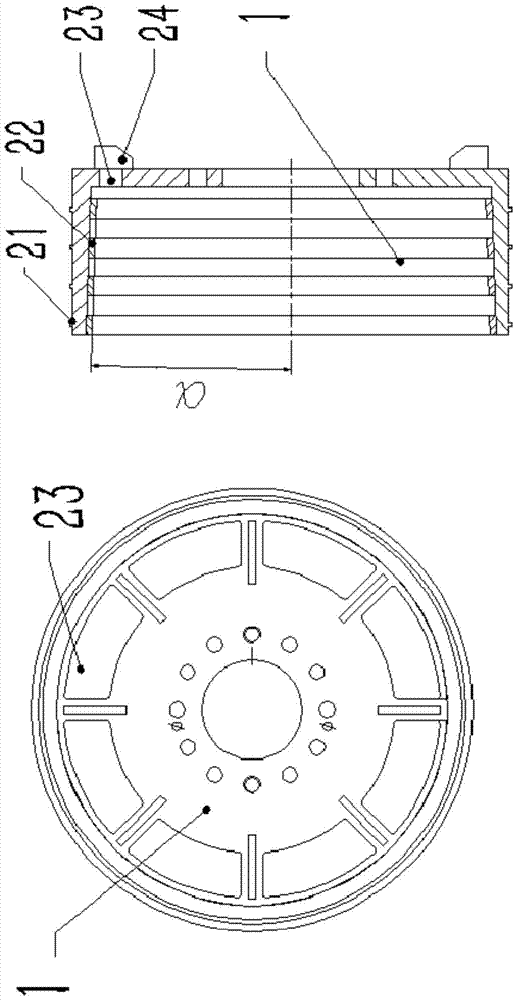
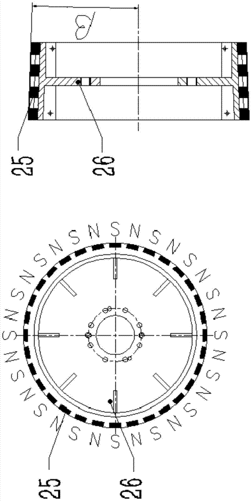
[0024] Such as figure 1 , figure 2 , image 3 , Figure 4 , Figure 5 , Image 6 , Figure 7 with Figure 8 As shown, the water-cooled permanent magnet energy-saving speed-regulating motor includes a motor housing, a motor rotor and a motor stator located in the motor housing, a motor rotor shaft that is coaxial with the motor housing and passes through the motor housing, The speed regulating assembly fixedly arranged at the left end of the motor housing to drive the axial movement of the motor rotor, the transient magnetic rotor fixedly arranged at the left end of the motor rotor shaft, the permanent magnetic rotor located in the transient magnetic rotor and fixedly connected with the load shaft, A cooling assembly for dissipating heat from the transient magnetic rotor; the load shaft is coaxial with the motor rotor shaft; the permanent magnet rotor is force-transmittingly connected to the transient magnetic rotor in the circumferential direction and is slidingly conne...


PUM


Abstract

The technology discloses a water-cooled permanent magnet energy-saving speed-regulating motor. The speed-regulating component includes a speed-regulating pull rod, a spiral groove transmission shaft, a spiral groove inner sliding sleeve, a spiral groove outer sliding sleeve and a speed-regulating bearing; the spiral groove inner sliding sleeve and the The motor housing is fixedly connected, the outer sliding sleeve of the spiral groove is set outside the inner sliding sleeve of the spiral groove; the inner sliding sleeve of the spiral groove is provided with a spiral groove, and the transmission shaft of the spiral groove is embedded in the spiral groove The sleeve is fixedly connected; the outer sliding sleeve of the spiral groove is fixedly connected with the drive shaft of the motor through the speed regulating bearing in the axial direction, and is rotationally connected in the circumferential direction; the speed regulating pull rod is fixedly installed on the outer sliding sleeve of the spiral groove; When the speed is adjusted by the speed pull rod, the spiral groove transmission shaft slides in the spiral groove of the spiral groove inner sliding sleeve to push the spiral groove outer sliding sleeve to move axially, and the speed regulating bearing fixed on the spiral groove outer sliding sleeve drives the motor rotor shaft along the axis to move. This technology realizes the purpose of stepless speed regulation, and has simple structure, good reliability and low maintenance cost.

Description

technical field [0001] The technology designs a permanent magnet energy-saving speed-regulating motor in the electromechanical field, and particularly relates to a water-cooled permanent magnet energy-saving speed-regulating motor. Background technique [0002] At present, in large industrial enterprises, such as chemical industry, cement, metallurgy and other industries, a large number of frequency converters are used in production due to the needs of the production process and the purpose of energy saving. Among them, the motors above 200 kW are mostly high-voltage motors. Especially for motors with a rated power above 400 kW, the voltage is basically 6000V or 10000V. The high-voltage frequency converter matched with the high-voltage motor has many disadvantages, mainly including: complex system, difficult maintenance and high cost. In addition, the harmonics it generates will pollute the power grid. For the electromagnetic induction speed controller, because of its sim...

Claims


Application Information

Patent Timeline
Patent Type & Authority Patents(China)
IPC IPC(8): H02K7/12H02K5/20H02K9/06
Inventor 高学田高超程娟其他发明人请求不公开姓名
Owner 南京银茂永磁节能科技有限公司
Features
  • R&D
  • Intellectual Property
  • Life Sciences
  • Materials
  • Tech Scout
  • Unparalleled Data Quality
  • Higher Quality Content
  • 60% Fewer Hallucinations
Learn More