
Frequency changer

A frequency converter and device technology, applied in the field of frequency converters, can solve problems such as difficult expansion and maintenance, unreasonable layout of internal components of frequency converters, waste of resources, etc., and achieve easy expansion and maintenance, manufacturing and installation, easy expansion and maintenance, and good heat dissipation performance effect

Active Publication Date: 2015-07-22
CSR ZHUZHOU ELECTRIC LOCOMOTIVE RES INST
View PDF6 Cites 13 Cited by
  • Summary
  • Abstract
  • Description
  • Claims
  • Application Information

AI Technical Summary

Problems solved by technology

[0002] At present, there are various designs of frequency converters. Some frequency converters have poor heat dissipation performance due to the unreasonable layout of internal components. Capacitor bursting, etc., which greatly affect the service life of the components and the safety of the inverter; some inverter designs can only complete a single function, so when it is necessary to use new energy to achieve AC motor speed regulation and grid-connected power generation At the same time, it is necessary to use frequency converters with two functions at the same time, which causes the problems of high price and large area occupation of the frequency converter when it is used, resulting in waste of resources; in addition, the existing frequency converters still have unreasonable general assembly, It is not easy to expand and maintain problems, which not only increases the production cost of the frequency converter, but also increases the assembly cost of the internal components of the frequency converter

Method used


Image

  • Frequency changer
  • Frequency changer
  • Frequency changer

Examples


Embodiment Construction

[0029] The present invention will be further described below in conjunction with accompanying drawing.

[0030] The particulars presented here are exemplary and used for illustrative discussion of embodiments of the invention only, and are presented to provide what is believed to be the most useful and understandable description of the principles and conceptual aspects of the invention. Regarding this point, there is no attempt to introduce the structural details of the present invention beyond the level required for a basic understanding of the present invention. Those skilled in the art can clearly understand how to implement the present invention in practice through the description and accompanying drawings. Several forms.

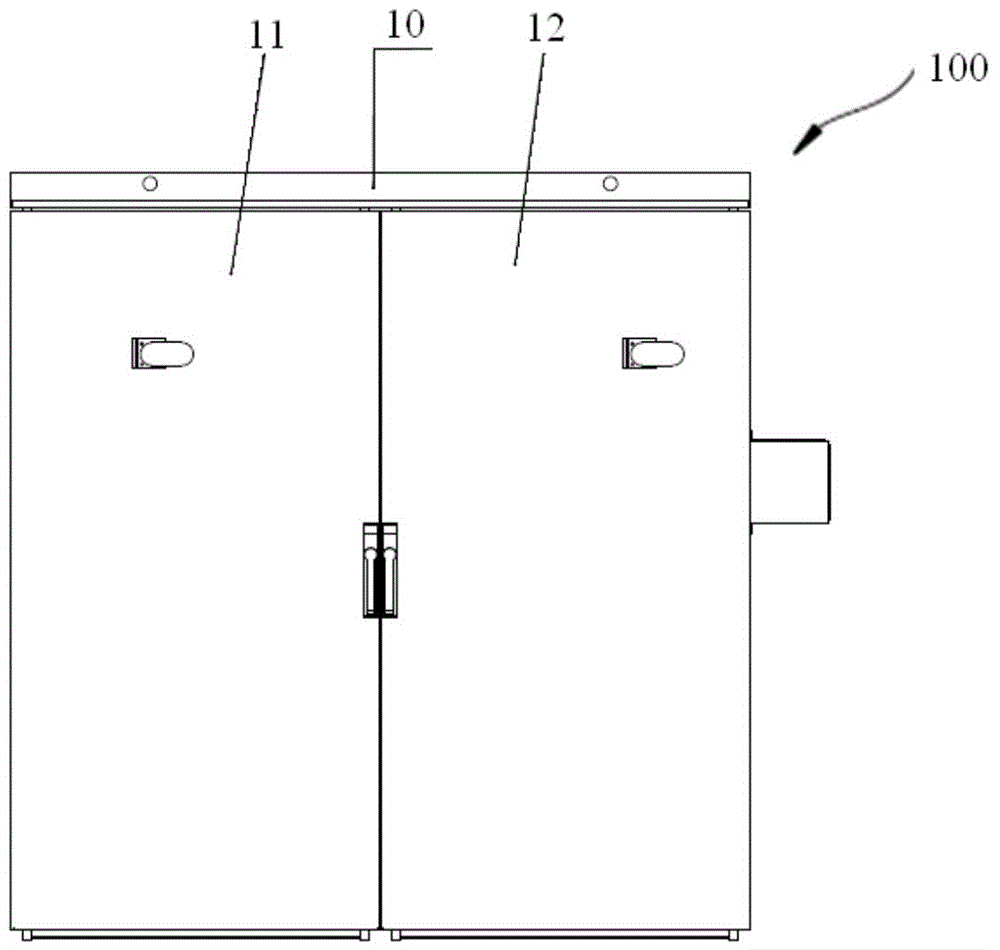
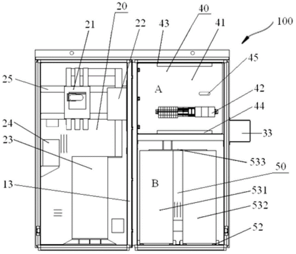
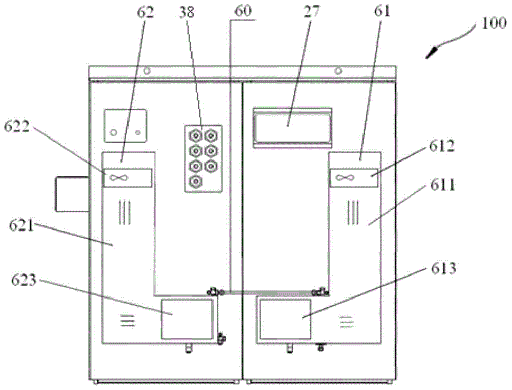
[0031] figure 1 , figure 2 A schematic diagram of the structure of the frequency converter 100 according to the present invention and a schematic diagram of the internal structure of the frequency converter 100 are shown respectively. A frequency co...


PUM


Abstract

The invention discloses a frequency changer which comprises a cabinet, a modularized component and a radiator component. The modularized component is arranged in the cabinet, the radiator component is arranged outside the cabinet, the modularized component comprises an alternating-current branch device set, a direct-current branch device set, an electrical device set and a power device set, the cabinet is divided into a first cabinet and a second cabinet through a partition, the first cabinet is used for containing the alternating-current branch device set, and the second cabinet comprises a first area used for containing the electrical device set, a second area used for containing the power device set, and a third area used for containing the direct-current branch device set. The modularized component is arranged reasonably, so that the frequency changer is enabled to be more reasonable and compact in assembly structure and easy to expand, maintain, manufacture and mount. In addition, power grid composite power supply and grid-connected power generation of the frequency changer can be realized, and the frequency changer has needed using functions and is good in heat radiating performance.

Description

technical field [0001] The invention relates to an electric device, in particular to a frequency converter. Background technique [0002] At present, there are various designs of frequency converters. Some frequency converters have poor heat dissipation performance due to unreasonable layout of internal components. Capacitor bursting, etc., which greatly affect the service life of the components and the safety of the inverter; some inverter designs can only complete a single function, so when it is necessary to use new energy to achieve AC motor speed regulation and grid-connected power generation At the same time, it is necessary to use frequency converters with two functions at the same time, which causes the problems of high price and large area occupation of the frequency converter during use, resulting in waste of resources; in addition, the existing frequency converters still have unreasonable general assembly, It is difficult to expand and maintain problems, which no...

Claims


Application Information

Patent Timeline
Patent Type & Authority Applications(China)
IPC IPC(8): H02M1/00H05K7/20
Inventor 冯江华尚敬胡家喜俞鹏程王婷李宇刘海涛梁志伟李彦涌从静何亚屏刘雨欣杨卓
Owner CSR ZHUZHOU ELECTRIC LOCOMOTIVE RES INST
Learn More