Device for dehydrating mops

A mop and mop head technology, which is applied in the field of machinery, can solve the problems affecting the drying degree of the mop, affecting the use state of the operator, and affecting the stability of the mop, and achieves a clean, simple structure, firm and compact clamping Effect

Inactive Publication Date: 2017-04-12
浙江九龙山实业股份有限公司
View PDF2 Cites 0 Cited by
  • Summary
  • Abstract
  • Description
  • Claims
  • Application Information

AI Technical Summary

Problems solved by technology

[0005] 1) When the motor located at the bottom of the side of the barrel starts to run, it will drive the barrel and the mop head in the barrel to rotate together, so as to achieve the purpose of drying the mop head. However, the mop head will shake off the water under the action of centrifugal force Dry, the higher the speed of the motor, the higher the degree of drying of the mop. Therefore, when the bucket starts to work, the motor is always in a high-speed rotating state, which increases the working noise on the one hand, and on the other hand, once the speed of the motor drops, Moisture on the mop head cannot be shaken out, and the mop cannot be wrung out, which is not conducive to cleaning the floor;
[0006] 2) In addition, when the mop is shaking water, the rod of the mop needs to be held by the operator, and when the mop head rotates, it will vibrate, and this vibration will be transmitted to the operator's hand through the mop rod, so that On the one hand, it affects the use status of the operator, on the other hand, it also affects the stability of the mop when it is shaking water, and further affects the degree of water drying of the mop

Method used


Image

  • Device for dehydrating mops
  • Device for dehydrating mops
  • Device for dehydrating mops

Examples


Embodiment Construction

[0032] The present invention will be described in further detail below in conjunction with the accompanying drawings and specific embodiments.

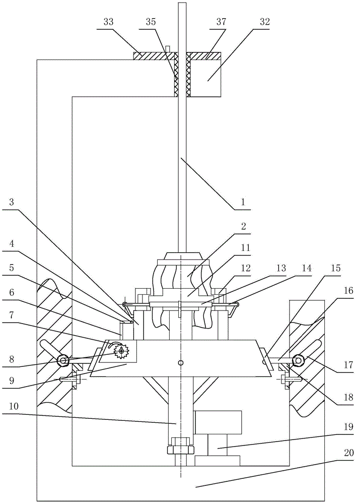
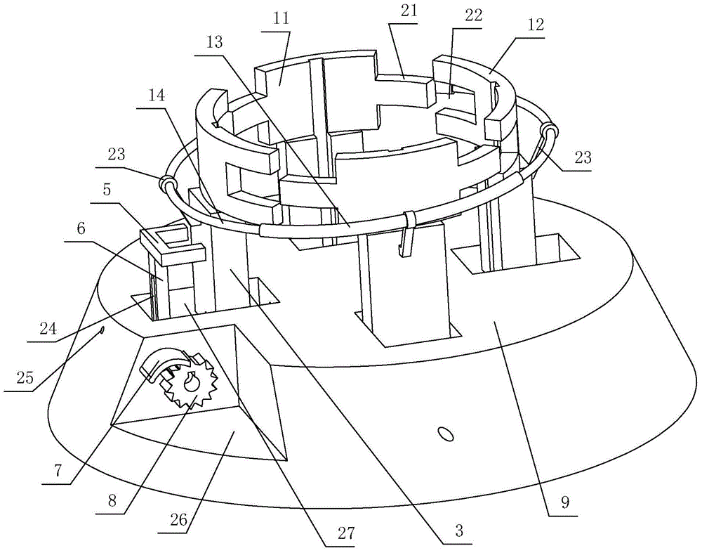
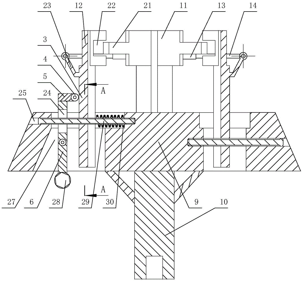
[0033] Depend on Figure 1 to Figure 8 As can be seen from the structural schematic diagram of the device for mop dehydration shown in the present invention, it includes a motor 19, a support base 20, a connecting support 10, a round table 9, a mop rod clamping device, a mop head clamping device and a mop head clamping drive device. The bottom of the support base 20 is U-shaped, the motor 19 is mounted on the bottom of the support base 20 and the output shaft of the motor 19 is connected to the lower end of the connecting base 10 through a transmission mechanism, and the upper end of the connecting base 10 is connected to the bottom of the round table 9. The bottom is fixedly connected, and the bottom of the connecting support 10 is rotatably connected with the bottom of the support base 20 . The mop head clamping device is connecte...


PUM


Abstract

The invention discloses a device for dewatering a mop. The device comprises a circular truncated cone, a mop rod clamping device, a mop head clamping device and a mop head clamping driving device, wherein the mop head clamping driving device comprises a ratchet wheel, pawl, a balance weight block, a swing rod and a horizontal U-shaped pressing rod; the upper end of the swing rod is fixedly connected with the U-shaped pressing rod; the middle part of the swing rod is hinged to the circular truncated cone; the balance weight block is fixedly connected to the lower end of the swing rod; the rod parts of the two free ends of the U-shaped pressing rod are pressed against the mop head clamping device; the ratchet wheel is fixedly connected to a hinge pin shaft of the swing rod and the circular truncated cone; one end of the pawl is hinged to the circular truncated cone, and the other end of the pawl is clamped with the ratchet wheel. By adoption of the structure, the working noise is greatly reduced, and the mop can be dried more deeply, so that cleaning the ground is facilitated; meanwhile, the mop head clamping driving device adopts a structure for combining the balance weight block with the swing rod; the device for dewatering the mop is simple in structure and convenient to operate.

Description

technical field [0001] The invention relates to the technical field of machinery, in particular to a mop dehydration device for wringing out the moisture on the mop. Background technique [0002] At present, there are various mops on the market, including flat mops, collodion mops and cloth mops. People can choose different types of mops according to different usage occasions, and cloth mops are the most widely used. The way of wringing out the traditional cloth mop is very laborious. It has to wring the mop in opposite directions with both hands to wring out the mop, but due to the limitation of manpower, the wringing effect is not good. Therefore, a kind of mop-drying bucket stepped on by feet has appeared again on the market. [0003] As disclosed on the website of the State Intellectual Property Office, the publication number is CN101926634A's invention patent "mop cleaning and drying bucket", which discloses a bucket body, a water rejection frame, a stirring plate, a p...

Claims


Application Information

Patent Timeline
Patent Type & Authority Patents(China)
IPC IPC(8): A47L13/58
Inventor 陈阳进
Owner 浙江九龙山实业股份有限公司
Why Eureka
Try Eureka