Large pentahedral gantry machining center and method for compensating deformation of movable cross beam

A technology of machining center and moving beam, applied in the field of precision parts processing, can solve the problems of inability to guarantee the stability of machining accuracy, affecting machining accuracy and efficiency, and pressing and deforming the moving beam, so as to achieve stable and reliable transmission accuracy and follow-up. The effect of high error and fast compensation speed

Inactive Publication Date: 2015-07-29
GUANGDONG UNIV OF TECH
View PDF8 Cites 6 Cited by
  • Summary
  • Abstract
  • Description
  • Claims
  • Application Information

AI Technical Summary

Problems solved by technology

However, some parts with high precision requirements in the industry cannot guarantee the stability of long-term machining accuracy, resulting in high scrap rate, low efficiency and low output.
Some large-scale pentahedral gantry machining centers can carry out powerful and heavy-duty cutting and processing of large and heavy-duty workpiece pentahedrons, and can complete five-coordinate and linkage CNC machining of spatial surfaces. However, the shortcomings of existing large-scale pentahedron gantry machining centers are the In the process of processing large molds, the stability is not good, so that it directly affects the processing accuracy and adding efficiency
In addition, the moving beam is the key part of the gantry machining center. The existing moving beam is generally installed on the column, the middle is suspended, the saddle and the ram are pressed on the moving beam, and the gravity will cause the moving beam to deform under the pressure. In addition, due to the sliding Components such as pillows and sliding saddles are forward-leaning structures, which generate a forward overturning force on the moving beam, resulting in deformation of the moving beam

Method used


Image

  • Large pentahedral gantry machining center and method for compensating deformation of movable cross beam
  • Large pentahedral gantry machining center and method for compensating deformation of movable cross beam

Examples


Embodiment Construction

[0018] The key technical points of the present invention will be described in further detail below in conjunction with the embodiments and accompanying drawings, but the embodiments of the present invention are not limited thereto.

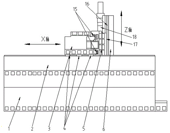
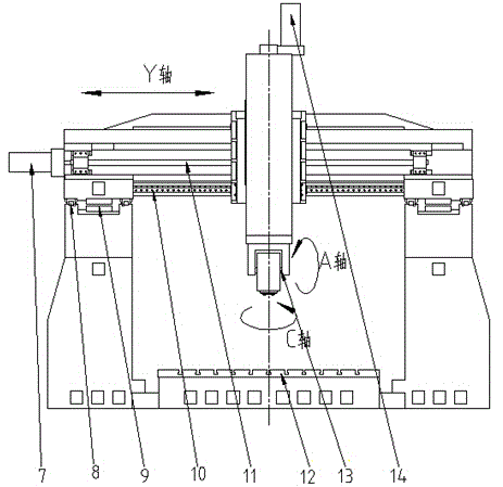
[0019] The structure diagram of the present invention is as figure 1 As shown, the large-scale pentahedron gantry machining center of the present invention includes left and right columns 1, fixed beam 2, moving beam 3, X-axis slider 4, sliding saddle 5, ram 6, Y-axis drive motor 7, and X-axis linear Guide rail 8, X-axis linear motor 9, Y-axis linear guide rail 10, worktable 12, spindle unit 13, Z-axis drive motor 14, Y-axis slider 15, Z-axis linear guide rail 16, Z-axis slider 17, of which the workbench 12 is installed on the ground, the left and right columns 1 are installed on both sides of the workbench 12, the left and right columns 1 support two fixed beams 2, and the two fixed beams 2 are respectively installed on the left and right columns...


PUM


Abstract

The invention discloses a large pentahedral gantry machining center and a method for compensating the deformation of a movable cross beam. The machining center comprises two fixed cross beams, a moveable cross beam, a workbench and the like, wherein the two fixed cross beams are respectively arranged on a left upright post and a right upright post; an X-axis linear guide rail is arranged on the fixed cross beams; X-axis slide blocks are arranged on the X-axis linear guide rail; the moveable cross beam is connected with the X-axis slide blocks; an X-axis linear motor drives the X-axis slide blocks to move along the X-axis linear guide rail; a Y-axis linear guide rail is arranged on the moveable cross beam; Y-axis slide blocks are arranged on the Y-axis linear guide rail; a slide saddle is connected with the Y-axis slide blocks; a Y-axis driving motor drives the Y-axis slide blocks to move along the Y-axis linear guide rail; a Z-axis linear guide rail is arranged on the slide saddle; Z-axis slide blocks are arranged on the Z-axis linear guide rail; a ram is connected with the Z-axis slide blocks; a Z-axis driving motor drives the Z-axis slide blocks to move along the Z-axis linear guide rail; a main shaft unit comprises an A-shaft rotary driving shaft and a C-shaft rotary driving shaft and is arranged on the ram. The machining center is applied to the high-speed and high-precision machining places of large parts.

Description

technical field [0001] The invention is applicable to the field of precision parts processing, in particular to a large-scale pentahedron gantry machining center and a method for compensating the deformation of a moving beam, and belongs to the innovative technology of a large-scale pentahedron gantry machining center and a method for compensating for the deformation of a moving beam. Background technique [0002] There are few special machine tools for five-sided machining at home and abroad, and many of them are processed by combining multiple machine tools and can be completed by multiple clamping. However, some parts with high precision requirements in the industry cannot guarantee the stability of long-term machining accuracy, resulting in a situation of high scrap rate, low efficiency and low output. Some large-scale pentahedral gantry machining centers can carry out powerful and heavy-duty cutting and processing of large and heavy-duty workpiece pentahedrons, and can ...

Claims


Application Information

Patent Timeline
Patent Type & Authority Applications(China)
IPC IPC(8): B23Q1/01B23Q1/62B23Q5/40B23Q15/18
CPCB23Q1/015B23Q1/01B23Q1/012B23Q1/62B23Q5/402B23Q15/18
Inventor 邓耀华刘夏丽吴黎明张巧芬王桂棠唐露新
Owner GUANGDONG UNIV OF TECH
Why Eureka
Try Eureka