Mechanical arm used for propeller boss detection

A technology of manipulators and hubs, which is applied in the field of manipulators for shaft and hub detection, can solve the problems of high labor intensity, large investment of manpower, and large detection errors, etc., and achieve good automation effects, improve detection efficiency, and reduce operating intensity.

Active Publication Date: 2015-07-29
SOHBI CRAFT CHANGSHU
View PDF10 Cites 9 Cited by
  • Summary
  • Abstract
  • Description
  • Claims
  • Application Information

AI Technical Summary

Problems solved by technology

[0003] In the prior art, due to the lack of an automatic device that can move the hub to be tested between the detection stations, it is usually carried out manually by the detection worker. One of the self-evident shortcomings of manual operation is that the detection personnel labor High intensity and low efficiency; second, a lot of manpower is invested, wasting precious labor resources; third, the detection error is large, and it is difficult to ensure quality, because the quality of manual detection is related to factors such as the experience, emotion, and sense of responsibility of the testing workers
[0004] The applicant has searched the literature, but there is no enlightenment to solve the above technical problems in the Chinese and foreign patents and non-patent literature published so far

Method used


Image

  • Mechanical arm used for propeller boss detection
  • Mechanical arm used for propeller boss detection
  • Mechanical arm used for propeller boss detection

Examples


Embodiment Construction

[0021] In order to enable the examiners of the patent office, especially the public, to understand the technical essence and beneficial effects of the present invention more clearly, the applicant will describe in detail the following in the form of examples, but none of the descriptions to the examples is an explanation of the solutions of the present invention. Any equivalent transformation made according to the concept of the present invention which is merely formal but not substantive shall be regarded as the scope of the technical solution of the present invention.

[0022] In the following descriptions, all concepts involving up, down, left, right, front and rear directionality (or orientation) are for the position state of the picture being described, and the purpose is to facilitate the public Therefore, it cannot be understood as a special limitation on the technical solution provided by the present invention.

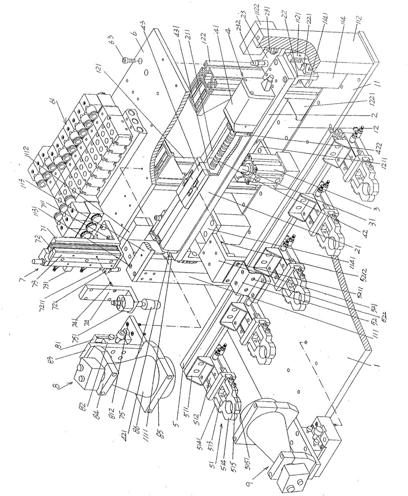
[0023] See figure 1 , shows a detection workbench 1, th...


PUM


Abstract

The invention discloses a mechanical arm used for propeller boss detection and belongs to the technical field of automated machines. The mechanical arm comprises a detecting worktable, a lifting beam, a lifting beam driving acting cylinder, a mechanical arm moving beam driving mechanism, a mechanical arm moving beam, a top plate, a plug track lifting mechanism, an overlook photographic mechanism and a horizontal photographic mechanism, wherein a guide rail stand column bottom plate and a main stand column bottom plate are fixed on the detecting work table; a left guide rail stand column is fixed at the left end of the guide rail stand column bottom plate while a right guide rail stand column is fixed at the right end of the guide rail stand column bottom plate; a lifting beam left sliding guide rail is fixed on one side of the left guide rail stand column; a lifting beam right sliding guide rail is fixed on one side of the right guide rail stand column; a left main stand column is fixed at the left end of the stand column bottom plate while a right main stand column is fixed at the right end of the stand column bottom plate; a sliding seat guide rail is arranged at the upper part of the lifting beam; the lifting beam driving acting cylinder is fixed on the guide rail stand column bottom plate; the mechanical arm moving beam driving mechanism is arranged on the lifting beam; the mechanical arm moving beam is connected with the mechanical arm moving beam driving mechanism; an electronic control valve is arranged on the top plate; the plug track lifting mechanism is arranged at the left end of the front side of the top plate; the overlook photographic mechanism is arranged on the top plate; the horizontal photographic mechanism is arranged on the detecting work table. The mechanical arm used for the propeller boss detection is high in detection efficiency and capable of reducing the manpower investment and ensuring the detection quality.

Description

technical field [0001] The invention belongs to the technical field of automatic machinery, and in particular relates to a manipulator for shaft hub detection. Background technique [0002] The aforementioned hub mainly refers to the hub used in the steering wheel of the structural system of the automobile steering system. The hub is small in size but has extremely strict quality requirements. In order to ensure the quality of the hub, it is necessary to test the inner tapered hole of the hub, that is, the conical hole of the hub, the hexagonal surface of the hexagonal head at one end of the hub, and even the weight of the hub. For plug gauges, vernier calipers or similar tools are usually used for the inspection of the hexagonal head, and a weighing device is usually used for the inspection of the weight. [0003] In the prior art, due to the lack of an automatic device that can move the hub to be tested between the detection stations, it is usually carried out manually b...

Claims


Application Information

Patent Timeline
Patent Type & Authority Applications(China)
IPC IPC(8): B25J11/00G01D21/02
Inventor 钱晓峰潘虎谢利峰刘阳
Owner SOHBI CRAFT CHANGSHU
Why Eureka
Try Eureka