
Intelligent window

A smart window and steering gear technology, applied in the field of intelligent systems, can solve problems such as poor practicability, slow response, and short service life, and achieve the effects of simple composition, fast response, and long service life

Inactive Publication Date: 2015-07-29
HENAN POLYTECHNIC UNIV
View PDF7 Cites 15 Cited by
  • Summary
  • Abstract
  • Description
  • Claims
  • Application Information

AI Technical Summary

Problems solved by technology

Gao Suping and others proposed an intelligent window control system based on PLC control technology and wireless communication technology in 2009, which focuses on building automatic control; however, this scheme does not give the specific structure of the window, and the research on window control is not deep enough
Based on the research of ordinary sliding window structure, Xie Zuomin et al. used a belt transmission structure to drive the window movement, and basically realized the intelligent control of the window. However, this technology has problems such as short service life, slow response, poor sensitivity, and low control accuracy, and the implementation of the scheme still remains have greater difficulty
In 2011, Li Shuo from Harbin Institute of Technology and others discussed the design scheme of the software and hardware system of smart windows. The blinds were used as the research object and the stepper motor was used as the drive to achieve the expected functions, but its practical value is not high, such as the lifespan is low , slow response, poor control accuracy, etc.
[0003] It can be seen that in the prior art, the research on smart windows exists or tends to be partial and one-sided research, or the overall research has problems such as poor practicability, cannot achieve full-open or fixed-angle precise control, low life, slow response, Poor control accuracy

Method used


Image

  • Intelligent window
  • Intelligent window
  • Intelligent window

Examples


Embodiment Construction

[0018] In order to make the purpose, technical solution and advantages of the present invention clearer, the present invention will be further described in detail below in conjunction with the accompanying drawings and specific embodiments.

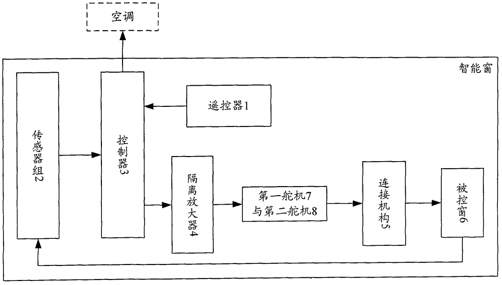
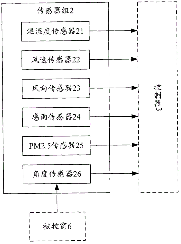
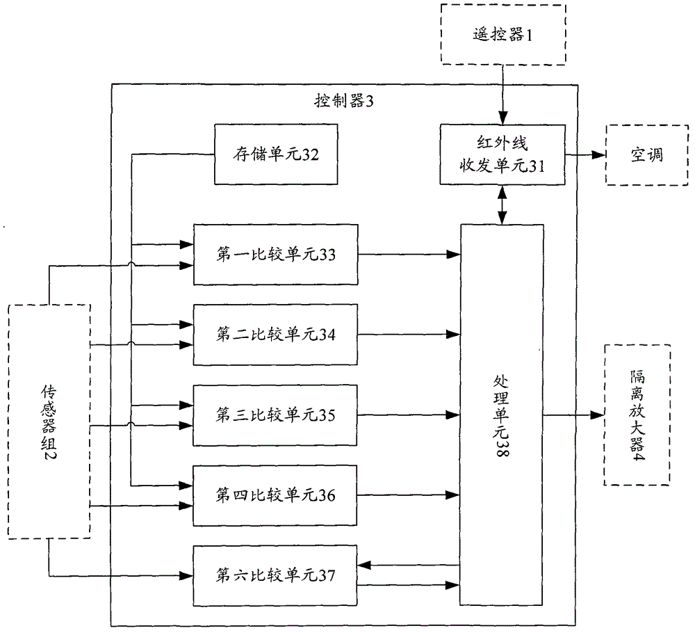
[0019] figure 1 It is a schematic diagram of the overall composition and structure of the smart window of the present invention. Such as figure 1 As shown, the smart window of the present invention includes: a remote controller 1, a sensor group 2, a controller 3, an isolation amplifier 4, a synchronously working first steering gear 7 and a second steering gear 8, a controlled window 6, and a connection structure 5 ; Wherein, the first steering gear 7 and the second steering gear 8 are installed on the walls of the upper and lower ends of the inner side of the fixed side of the controlled window 6; the first steering gear 7, the second steering gear 8 and the controlled window 6 pass through Connecting mechanism 5 is fixedly connected; ...


PUM


Abstract

The invention provides an intelligent window which comprises a remote controller, a sensor group, a controller, an isolation amplifier, a first steering engine, a second steering engine, a controlled window and a connecting structure, wherein the first steering engine and the second steering engine are mounted on walls at the upper end and the lower end of the outer side of a fixed edge of the controlled window, and the first steering engine, the second steering engine and the controlled window are fixedly connected through the connecting structure. The intelligent window has the advantages of high sensitivity and control precision, fine stability, simple structure, assembly flexibility, convenience in use and the like, and can be widely applied to production and life.

Description

technical field [0001] The invention relates to an intelligent system, in particular to an intelligent window control system. Background technique [0002] At present, in 2001, Deng Xuexin and others put forward the conceptual design of smart windows. Under the guidance of the design concept of "requirement analysis-goal establishment-functional structure analysis-multiple scheme generation-scheme evaluation", the early smart window scheme was formulated, which provided a reasonable reference for the design of smart windows. Gao Suping et al. proposed an intelligent window control system based on PLC control technology and wireless communication technology in 2009, which focuses on building automatic control; but this scheme does not give the specific structure of the window, and the research on window control is not deep enough. Based on the research of ordinary sliding window structure, Xie Zuomin et al. used a belt transmission structure to drive the window movement, and...

Claims


Application Information

Patent Timeline
IPC IPC(8): E05F15/71E05F15/78
Inventor 张素妍朱贞卫张路遥陈昌亚杨俊斌高杨吴海波
Owner HENAN POLYTECHNIC UNIV
Learn More