High pressure resistant magnetic pump

A high-pressure resistant magnetic pump technology, applied in pumps, pump devices, pump components, etc., can solve the problem of increasing the matching gap between the inner magnetic rotor 5 and the outer magnetic rotor 6, affecting the efficiency of magnetic coupling transmission, and limiting the outlet pressure of the magnetic pump To achieve the effect of improving the efficiency of magnetic coupling transmission, improving the safety of use, and reducing eddy current loss

Active Publication Date: 2015-07-29
DANDONG TOP PUMP
View PDF5 Cites 4 Cited by
  • Summary
  • Abstract
  • Description
  • Claims
  • Application Information

AI Technical Summary

Problems solved by technology

[0005] Due to the limitation of the magnetic gap of the inner and outer magnetic rotors and the influence of eddy current loss, the wall thickness of the spacer 7 cannot be designed to be arbitrary to meet the pressure intensity requirements, so the outlet pressure of the magnetic pump is greatly restricted, and the design lift of the pump is limited. The corresponding impact limits the application of the magnetic pump in high pressure and high lift conditions, especially when the magnetic pump is used as a secondary pump, the isolation sleeve 7 of the magnetic pump will bear higher pressure
[0006] In addition, the spacer sleeve 7 will expand and deform under the action of pressure, so it is necessary to increase the matching gap between the inner magnetic rotor 5 and the outer magnetic rotor 6 accordingly, which will affect the efficiency of magnetic coupling transmission.
[0007] Magnetic pumps are often used in the transportation of toxic and flammable media. Once the isolation sleeve 7 is broken due to pressure damage, the safety consequences caused by media leakage are serious.

Method used


Image

  • High pressure resistant magnetic pump
  • High pressure resistant magnetic pump
  • High pressure resistant magnetic pump

Examples


Embodiment Construction

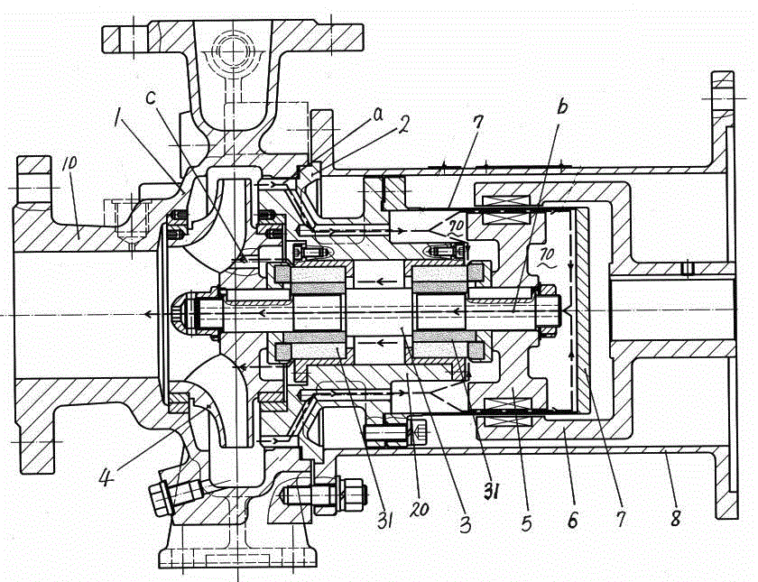
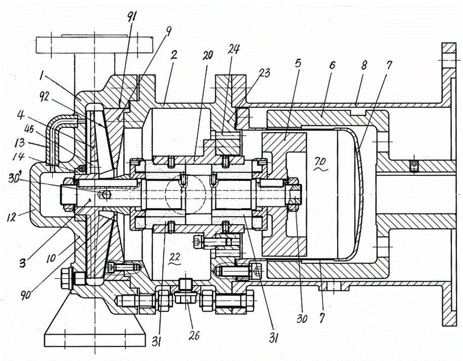
[0019] The present invention includes a pump body 1, a pump cover 2, a pump shaft 3, an impeller 4, an inner magnetic rotor 5, an outer magnetic rotor 6, an isolation sleeve 7, a connecting frame 8, a drive shaft, and a drive shaft bearing box. The pump shaft 3 passes through The bearing device 31 is installed in rotation with the bearing housing 20 on the pump cover 2, the impeller 4 is fixedly installed on the front shaft end of the pump shaft 3 in the pump body 1, and the inner magnetic rotor 5 is fixedly installed on the rear shaft end of the pump shaft 3 , the outer magnetic rotor 6 is fixedly installed on the shaft end of the drive shaft, a spacer 7 is set between the inner magnetic rotor 5 and the outer magnetic rotor 6, the spacer 7 is sealed and fixedly connected with the pump cover 2, and the pump body 1 and the pump cover 2 are docked and fixed Connection, the connecting frame 8 is docked and fixedly connected with the pump cover 2, and the drive shaft bearing box is...


PUM


Abstract

The invention discloses a high pressure resistant magnetic pump, which comprises a pump body (1), a pump cover (2), a pump shaft (3), an impeller (4), an internal magnetic rotor (5), an external magnetic rotor (6), an isolation sleeve (7), a connection frame (8), a drive shaft and a drive shaft bearing box; a spacing ring (9) is fixedly connected by a bolt through match with a spigot of the pump cover (2) in the pump body (1) so as to form the side wall of a pump cavity; an internal annular hole (90) of the spacing ring (9) forms a liquid inlet of the pump cavity; the pump cover (2) is radially provided with a liquid inlet pipe port (21); the pump cover (2) is provided with a drainage liquid inlet (24); the center of the pump shaft (3) is provided with a flow returning hole (30). Pressure borne by an inner cavity (70) of the isolation sleeve is equal to the inlet pressure of the pump, the pressure resistance of the pump is improved, a bearing device (31) of the pump shaft is totally positioned in a flowing liquid inlet medium environment, the cooling effect is good, the machining is convenient, the production cost is reduced and the service life is long.

Description

technical field [0001] The present invention relates to a magnetic pump. In particular, the improvement of the inlet structure of the magnetic pump is more suitable for high inlet pressure conditions. Background technique [0002] The magnetic pump includes a pump body 1, a pump cover 2, a pump shaft 3, an impeller 4, an inner magnetic rotor 5, an outer magnetic rotor 6, an isolation sleeve 7, a connecting frame 8 and a drive shaft connected to the outer magnetic rotor 6, and a drive shaft bearing box , the pump shaft 3 is rotated and installed with the bearing seat sleeve 20 on the pump cover 2 through the bearing device 31, the impeller 4 is fixedly installed on the front shaft end of the pump shaft 3 in the pump body 1, and the inner magnetic rotor 5 is fixedly installed on the pump shaft On the rear shaft end of 3, the outer magnetic rotor 6 is fixedly installed on the shaft end of the drive shaft, and a spacer 7 is arranged between the inner magnetic rotor 5 and the ou...

Claims


Application Information

Patent Timeline
Patent Type & Authority Applications(China)
IPC IPC(8): F04D13/02F04D29/42F04D29/046F04D29/00F04D7/02
CPCF04D7/02F04D13/02F04D29/007F04D29/046F04D29/426F04D29/586
Inventor 徐云显李岩孙玉全于开勇徐海明
Owner DANDONG TOP PUMP
Why Eureka
Try Eureka