Complex radial flow pump, combined radial flow pump and air extraction system

A technology of radial flow and air extraction grooves, which is applied to radial flow pumps, parts of pumping devices for elastic fluids, pumps, etc., which can solve the problem of low linear velocity inside the rotor flat plate, reduced air extraction performance of radial flow pumps, and reduced Radial flow molecular pump pumping performance and other issues, to achieve the effect of saving pumping energy consumption, saving equipment, and improving the quality of vacuum products

Active Publication Date: 2015-07-29
储继国
View PDF7 Cites 8 Cited by
  • Summary
  • Abstract
  • Description
  • Claims
  • Application Information

AI Technical Summary

Problems solved by technology

The radial flow pump uses the high-speed rotating rotor plate to pull the gas to achieve air extraction. The inner linear velocity of the rotor plate is low, resulting in the pumping speed of the inner part being significantly lower than that of the outer part. For radial flow pumps that pump air from the inside out, the pumping characteristics Contrary to the above pumping requirements, thus greatly reducing the pumping performance of the radial flow molecular pump
For the radial flow pump that pumps air from the outside to the inside, although the pumping characteristics are consistent with the general direction of the pumping requirements, however, when the working pressure is high (for example > 10Pa), the pumping speed decreases more than the gas volume. Therefore, also Reduced pumping performance of radial flow pumps

Method used


Image

  • Complex radial flow pump, combined radial flow pump and air extraction system
  • Complex radial flow pump, combined radial flow pump and air extraction system
  • Complex radial flow pump, combined radial flow pump and air extraction system

Examples


Embodiment 1

[0033] Embodiment one composite radial flow pump

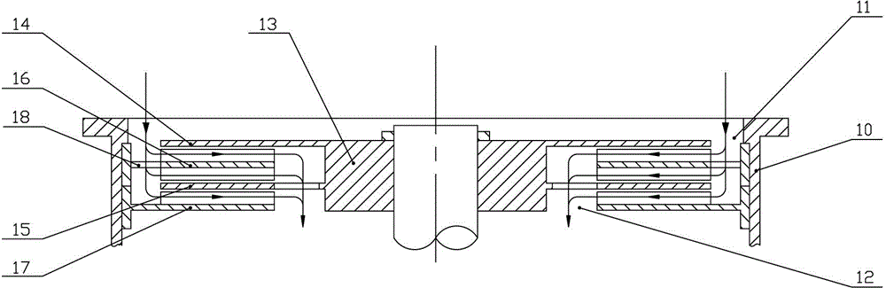
[0034] Such as Picture 1-1 As shown, Embodiment 1 of the present invention provides a composite radial flow pump, including a housing 10, the housing 10 is provided with an air inlet 11 and an exhaust port 12, and the housing 10 is provided with a rotor 13, a static wheel 16 and a dynamic seal 17, The rotor 13 is fixedly provided with two flat disc moving wheels 14, 15, and the stationary wheel 16 is arranged between the two moving wheels 14, 15, and the outer side of the stationary wheel 16 is provided with communicating air holes 18.

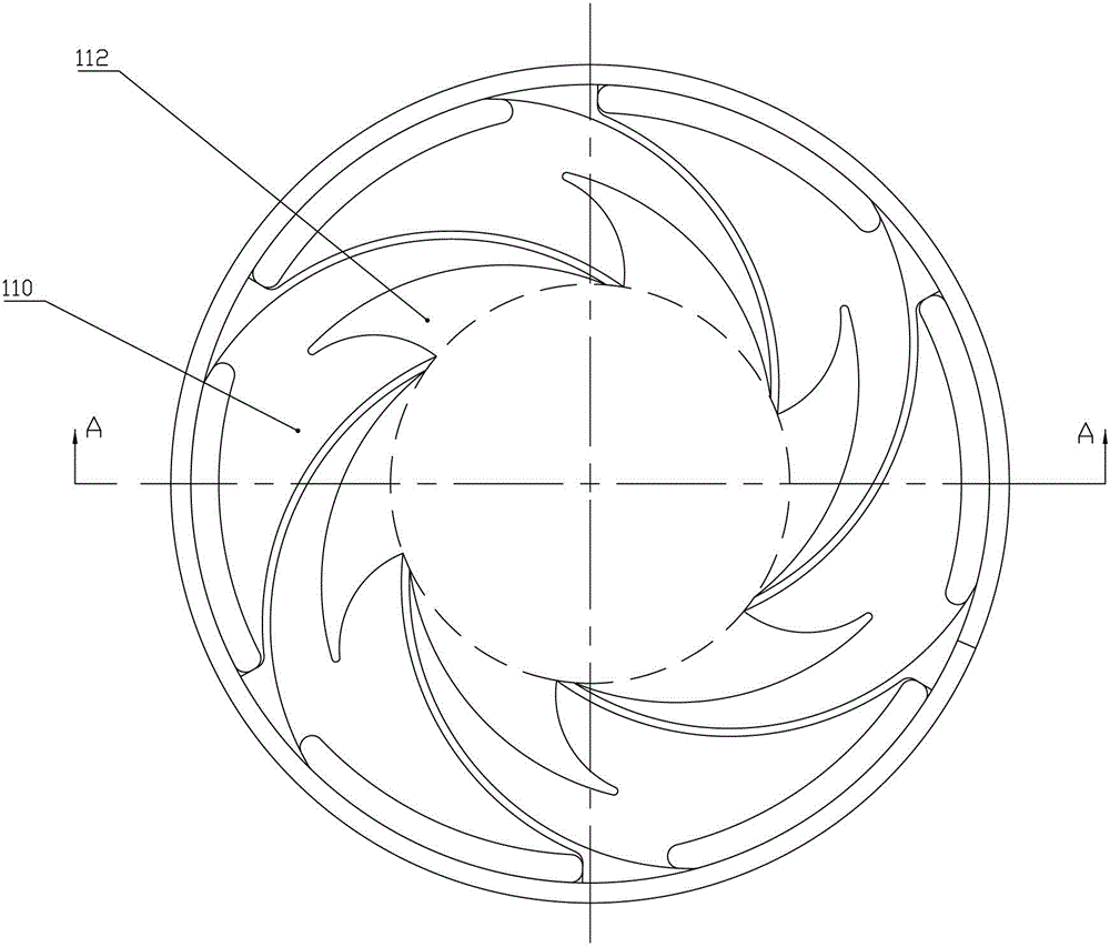
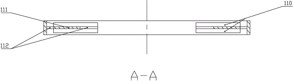
[0035] Such as Figure 1-2 and Figure 1-3 As shown, the upper and lower sides of the static wheel 16 are respectively provided with a number of spiral air suction grooves 110 of the same shape, and the air suction grooves 110 on the upper and lower sides of the static wheel 16 share a groove bottom 111, and the groove bottom 111 is provided with an opening 112. The opening 112 is used to...

Embodiment 2

[0039] Embodiment two combined radial flow pump

[0040] Such as figure 2 As shown, a combined radial flow pump provided by Embodiment 2 of the present invention includes a pump casing 20, an air inlet 21 and an exhaust port 22 are provided on the pump casing 20, a rotor 23 is arranged inside the pump casing 20, and the pump casing 20 The middle part is provided with a first air pumping stage 24, and the first air pumping stage 24 adopts 6 groups of parallel compound radial flow pumps as described in Embodiment 1, and the first air pumping stage 24 pumps air from the outside to the inside;

[0041] The two sides of the first pumping stage 24 are respectively provided with dynamic seals 25, and the outer sides of each dynamic seal 25 are respectively provided with a second pumping stage 26, and the second pumping stages 26 adopt two sets of parallel connection as described in the first embodiment. compound radial flow pump, the second pumping stage 26 pumps air from the ins...

Embodiment 3

[0045] Embodiment 3 The exhaust system of the compound radial flow pump low-pressure plasma discharge device

[0046] Such as image 3 As shown, the third embodiment provides an air pumping system for a compound radial pump low-pressure plasma discharge device, including a discharge chamber 30, which is connected to a roughing pump 32 through a first vacuum valve 31, and the discharge chamber is also connected to a roughing pump 32 through a first vacuum valve 31. Two vacuum valves 36 are connected with the radial flow pump 35, the composite radial flow pump 35 is connected with the backing pump 33 through the third vacuum valve 34, the discharge chamber 31 is also connected with the working gas container 39 through the fourth vacuum valve 38, and the discharge chamber 31 is also connected with the working gas container 39 respectively. The vacuum gauge 37 is connected to the purge valve 310 .

[0047] Wherein, the rough pump 32 is only used for the pumping of the rough pum...


PUM


Abstract

The invention provides a complex radial flow pump. The complex radial flow pump comprises a shell, wherein air inlets and air exhausts are formed in the shell, a rotor, a static wheel and a dynamic seal are arranged in the shell, two moving wheels are fixedly arranged on the rotor, the static wheel is arranged between the two moving wheels, and a communication air hole is formed in the outer side of the static wheel; spiral air extraction grooves with the same shape are formed in the upper side and the lower side of the static wheel respectively, and the air extraction grooves in the upper side of the static wheel and the air extraction grooves in the lower side of the static wheel share the same groove bottom, an opening is formed in the groove bottom, and the opening ratio of the opening ranges from 0% to 100%; the dynamic seal is located below the moving wheels, a plurality of spiral dynamic seal grooves are formed in the upper side of the dynamic groove and are used for separating the air inlets and the air exhausts of the air extraction grooves. According to the complex radial flow pump, because two traditional single-traction radial flow pumps are connected in parallel back to back, and the opening is formed in the groove bottom, the extraction speed is remarkably increased. The invention further provides a combined radial flow pump which comprises the complex radial flow pump, and three application embodiments of the complex radial flow pump.

Description

technical field [0001] The invention belongs to the technical field of obtaining vacuum, and in particular relates to a compound radial flow pump, a combined radial flow pump including the compound radial flow pump, and an air extraction system including the compound radial flow pump or the combined radial flow pump. Background technique [0002] At present, medium vacuum (pressure 0.1~100Pa) is a variety of high-end vacuum industries enhanced by low-pressure plasma (magnetron sputtering, cathode arc source, plasma enhanced chemical vapor deposition, etc.), as well as molecular distillation, freeze drying and electric capacitor Traditional Roots pumps and molecular pumps are widely used in the gathering section of industries such as industrial areas. Among them, Roots pumps are bulky, high in energy consumption, and there is oil vapor pollution, and the pumping speed of molecular pumps in this section is greatly increased. decline, or even can not run, affecting the developm...

Claims


Application Information

Patent Timeline
Patent Type & Authority Applications(China)
IPC IPC(8): F04D17/10F04D29/42F04D29/28F04D29/44F04D29/08F04D25/16F04D17/12H01G13/00B01D3/12F26B25/00F04B41/06F04B37/14
Inventor 储继国
Owner 储继国
Why Eureka
Try Eureka