Propeller shaft sealing structure of ship propeller

A technology of sealing structure and propeller, which is applied in the direction of water acting propulsion elements, transmission devices with synchronous propulsion components, transmission device parts, etc., can solve problems such as emulsification, ships cannot run normally, lubricating oil failure, etc., and achieve the goal of avoiding emulsification Effect

Inactive Publication Date: 2015-07-29
SMMC MARINE DRIVE SYST SUZHOU
View PDF6 Cites 12 Cited by
  • Summary
  • Abstract
  • Description
  • Claims
  • Application Information

AI Technical Summary

Problems solved by technology

[0003] Although the above sealing form can well prevent seawater from entering the gearbox and prevent oil leakage in the gearbox, if the sealing ring fails, it will emulsify the lubricating oil in the entire gearbox, resulting in failure of the lubricating oil
At present, the power of a single propeller has been developed to 4000kW, and the demand for lubricating oil per propeller is 3 to 4 tons. Once the seal ring of the propeller shaft fails, all lubricating oil will fail, and all lubricating oil will need to be replaced, resulting in huge economic waste
[0004] When a ship is navigating with high-power rudder propellers, especially in areas with poor water quality, sediment and dirt enter the frame oil seal from the gap between the cone ring and the hub body, destroying the sealing lip of the frame oil seal, resulting in seal failure, causing Water in the gearbox or oil leakage in the gearbox
As a result, the power propulsion device of the ship will eventually fail, and the ship will not be able to drive normally

Method used


Image

  • Propeller shaft sealing structure of ship propeller

Examples


Embodiment Construction

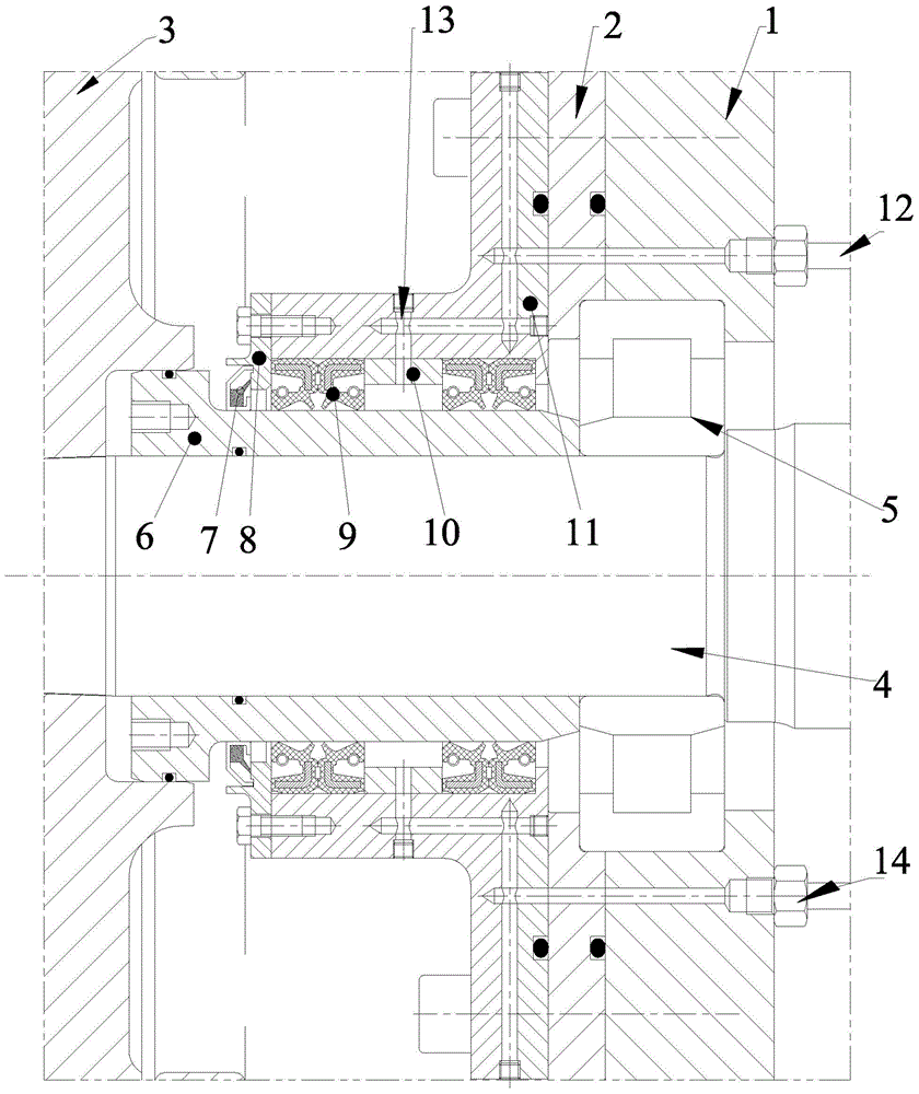
[0022] Such as figure 1 As shown, the marine propeller shaft seal structure includes seat ring 11, spacer ring 10, cover plate 8, seal 7 and rotating frame oil seal 9, seal 7 is TBR / 9RB type seal, and rotating frame oil seal 9 is TC The double-lip rubber-coated skeleton oil seal has a reinforcement ring made of stainless steel springs outside the lip. The seat ring 11 is fixed to the cone ring 2 by bolts. The cone ring 2 is installed on the gear box 1. The thermal spraying bush 6 passes through The interference fit is set on the paddle shaft 4, and the paddle shaft 4 is freely rotatably supported on the gear box 1 through the bearing 5. The four rotating skeleton oil seals are installed on the ceramic area of ​​the thermal spraying bushing 6, and the outer part of the rotating skeleton oil seal 9 diameter and the inner hole of the seat ring 11 for interference fit, and its inner diameter sealing lip is in contact with the ceramic area of ​​the thermal spraying bushing 6, where...


PUM


Abstract

The invention relates to a shaft sealing structure of a ship propeller. A race is fixedly connected with a conical ring; the conical ring is arranged on a gearbox body; a thermal spraying bushing sleeves a propeller shaft in an interference way; four rotary skeleton oil seals are arranged on a ceramic area of the thermal spraying bushing; the outer diameter of each rotary skeleton oil seal is in interference fit with an inner hole of the race; a sealing lip of the inner diameter is in contact with the ceramic area of the thermal spraying bushing; the sealing lip of the outermost rotary skeleton oil seal faces outwards, the sealing lip of the innermost rotary skeleton oil seal faces inwards, a space ring is arranged between the two middle rotary skeleton oil seals, and the space ring, the two middle rotary skeleton oil seals and the thermal spraying bushing form a cavity; a communicated gravity oil passage is arranged in the gearbox body, the conical ring, the race and the space ring, and is communicated with the cavity; a sealing part sleeves the thermal spraying bushing; a sealing lip of the sealing part is in contact with the vertical end surface of a cover plate. The propeller shaft sealing structure has the advantage that gravity oil is filled into the gravity oil cavity through the oil passage, so the seawater is prevented from entering the gearbox, and the emulsifying of lubricating oil is avoided.

Description

technical field [0001] The invention relates to a marine propeller shaft sealing structure, which belongs to the technical field of marine propellers. Background technique [0002] At present, the underwater propeller shaft seal of marine propellers adopts the following form: three TC rotating skeleton oil seals rotate on the thermal sprayed ceramic bushing, the oil seal lip and the bushing surface form a thin film for sealing, and one of them prevents lubricating oil from leaking. The other two prevent seawater from entering the inside of the gearbox. The existing structure has been tested in practice and can effectively seal the liquid. [0003] Although the above-mentioned sealing form can well prevent seawater from entering the gearbox and prevent the oil from leaking in the gearbox, if the sealing ring fails, it will emulsify the lubricating oil in the entire gearbox, resulting in failure of the lubricating oil. At present, the power of a single propeller has been dev...

Claims


Application Information

Patent Timeline
Patent Type & Authority Applications(China)
IPC IPC(8): F16H57/029F16H57/04B63H23/34
CPCF16H57/029B63H23/34F16H57/0423F16H57/0424
Inventor 李新刚
Owner SMMC MARINE DRIVE SYST SUZHOU
Why Eureka
Try Eureka