
Rapid measurement method for parallelism error of linear guide rails
A technology of straightness error and linear guide rail, which is applied in the direction of measuring devices, instruments, optical devices, etc., can solve problems such as low efficiency, waste of time, and cumbersome data processing.
Patent Information
- Authority / Receiving Office
- CN · China
- Current Assignee / Owner
- Publication Date
- 2015-07-29
- Estimated Expiration
- Not applicable · inactive patent
Smart Images
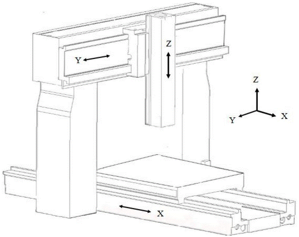
Figure 1 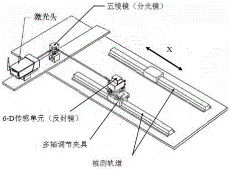
Figure 2 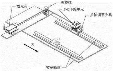
Figure 3
Abstract
Description
technical field
[0001] The invention relates to a fast measuring method for the parallelism error of a linear guide rail, which belongs to the field of machine tool precision design. Background technique
[0002] The worldwide competition in the equipment manufacturing industry has led to the development of machine tools in the direction of high precision and large scale. The parallelism error of the guideway, which has a very important impact on the performance of the machine tool, has always been concerned. Therefore, how to accurately, quickly and efficiently measure the parallelism error of the linear guide rail to improve the machining accuracy of the machine tool has important practical significance.
[0003] Parallelism tolerance is a kind of orientation tolerance, which is the allowable variation in the direction of the measured element relative to the datum. The commonly used instruments and methods for detecting the parallelism error of machine tool guide rails a...
Examples
Embodiment Construction
[0041] Taking the gantry-type five-axis processing machine tool as an example, the Cartesian coordinate system of the machine tool is established, such as Figure 5 shown. The invention adopts the XD series laser interferometer produced by the American Automatic Precision Engineering Company (API) to measure the straightness error of the x-direction rail of the gantry-type five-axis processing machine tool. The device involved in this method includes a laser head (composed of an interferometer host and a front-end interference mirror), a 6-D sensing unit (mirror), a pentaprism, an adjustment fixture, and a measured x-direction linear guide.
[0042] Step 1 Directly measure the straightness error of the linear guide a
[0043] 1. Plan N test sampling points
[0044] Plan N test sampling points on the measured x-direction linear guide rail 5 at equal intervals.
[0045] 2. Component installation and optical path alignment
[0046] After planning the test sampling points, it ...