Converter valve thyristor level damping loop parameter testing device and method

A thyristor-level, parametric testing technology, applied in measuring devices, measuring electrical variables, measuring resistance/reactance/impedance, etc., can solve the problems of reduced test accuracy, inaccurate test results, etc., to achieve convenient operation, simple structure, Test the exact effect

Active Publication Date: 2015-07-29
XUJI GRP +3
View PDF7 Cites 33 Cited by
  • Summary
  • Abstract
  • Description
  • Claims
  • Application Information

AI Technical Summary

Problems solved by technology

Compared with the traditional test method, this method has improved test speed and convenience, but because this test method uses three excitation sources with different frequencies, the capacitance value of the capacitor in the damping circuit will vary with the frequency of the external power supply. Therefore, the characteristics of the excitation source determine the inaccuracy of its test results, resulting in the reduction of its test accuracy.

Method used


Image

  • Converter valve thyristor level damping loop parameter testing device and method
  • Converter valve thyristor level damping loop parameter testing device and method
  • Converter valve thyristor level damping loop parameter testing device and method

Examples


Embodiment Construction

[0020] The present invention will be further introduced below in conjunction with the accompanying drawings and specific embodiments.

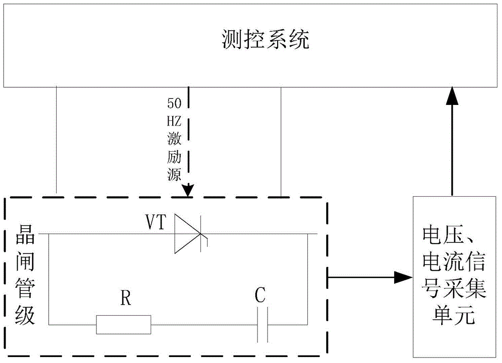
[0021] Such as figure 1 Shown is the schematic block diagram of the thyristor stage damping circuit parameter testing device of the converter valve of the present invention. It can be seen from the figure that the thyristor stage to be tested includes a thyristor VT and a damping circuit composed of a resistor R and a capacitor C1 connected in series, and the thyristor VT is connected in parallel with the damping circuit. The device includes a measurement and control system for applying an excitation source to the thyristor stage under test and a signal acquisition unit connected to the measurement and control system. The signal acquisition unit includes a voltage sensor and a measurement current for measuring the voltage signal at both ends of the damping loop during testing. The current sensor for the current signal of the damping loop is us...


PUM


Abstract

The invention discloses a converter valve thyristor level damping loop parameter testing device and method. The device comprises a measurement and control system used for applying an excitation source to a tested thyristor level, and a signal collection unit connected with the measurement and control system. The signal collection unit comprises a voltage sensor used for measuring voltage signals at the two ends of a damping loop in the testing process, a current sensor used for measuring current signals flowing through the damping loop, and an alternating-current power supply used for being applied to a measurement and control system of a thyristor level test object, wherein the frequency of an excitation source of the alternating-current power supply is 50 Hz. According to the method, the alternating-current power supply with the 50 Hz working frequency is applied to the two ends of the thyristor level test object, and meanwhile the damping resistance and the damping capacitance are calculated through the phase difference of the voltage and the current of the thyristor level test object. The testing device is simple in structure, convenient to operate and accurate in measurement. Due to the fact that the testing work condition of the device is completely the same with the actual running work condition of the converter valve thyristor level, the accuracy and reliability of the testing result of the testing device is determined by the characteristic.

Description

technical field [0001] The invention belongs to the technical field of high-voltage direct current transmission, and in particular relates to a device and method for testing parameters of a thyristor-level damping circuit of a converter valve. Background technique [0002] The converter valve is an important component in the HVDC transmission project, and the thyristor-level damping circuit is an important part of the converter valve. The damping circuit includes damping resistors and damping capacitors. Its function is to ensure uniform voltage distribution among thyristors, which is of great significance to the safe operation of DC transmission. Therefore, accurate testing of damping circuit component parameters is extremely important. [0003] The traditional method of testing the damping circuit is mainly to use a multimeter, an electric bridge, etc. for direct testing. This method needs to dismantle the original circuit and measure one by one, which can ensure the accu...

Claims


Application Information

Patent Timeline
Patent Type & Authority Applications(China)
IPC IPC(8): G01R27/26G01R27/08
Inventor 黄永瑞范彩云何青连毛文喜洪波王宇丁张志刚李芳芳
Owner XUJI GRP
Why Eureka
Try Eureka