
Workshop layout method of discrete manufacturing system

A layout method and technology for manufacturing systems, applied in general control systems, control/regulation systems, program control, etc., can solve the problem of unsatisfactory global optimization capability and calculation time performance, low search efficiency of genetic algorithm, slow convergence speed, etc. question

Inactive Publication Date: 2015-07-29
HAIAN COUNTY SHENLING ELECTRICAL APPLIANCE MFG
View PDF4 Cites 20 Cited by
  • Summary
  • Abstract
  • Description
  • Claims
  • Application Information

AI Technical Summary

Problems solved by technology

[0003] The general discrete manufacturing system workshop layout problem is a combinatorial optimization problem in two-dimensional space, which involves two sub-tasks, the allocation of equipment rows and the equipment sorting in the row. The existing typical layout design methods mainly include system layout design (SLP), integer programming, mixed integer programming, dynamic programming, and rule placement, these traditional methods are not ideal in terms of the global optimization ability of the scheme and calculation time, etc.
However, when solving optimization problems with complex and large-scale solution space structures such as workshop layout optimization, the general genetic algorithm still has the following two problems: First, because the genetic algorithm is based on the competition mechanism between organisms, the algorithm In the initial stage, better individuals can easily form an overwhelming advantage, causing the algorithm to fall into a local optimum; secondly, in the face of optimization problems with a huge solution space, the genetic algorithm has low search efficiency and slow convergence speed

Method used


Image

  • Workshop layout method of discrete manufacturing system
  • Workshop layout method of discrete manufacturing system
  • Workshop layout method of discrete manufacturing system

Examples


Embodiment Construction

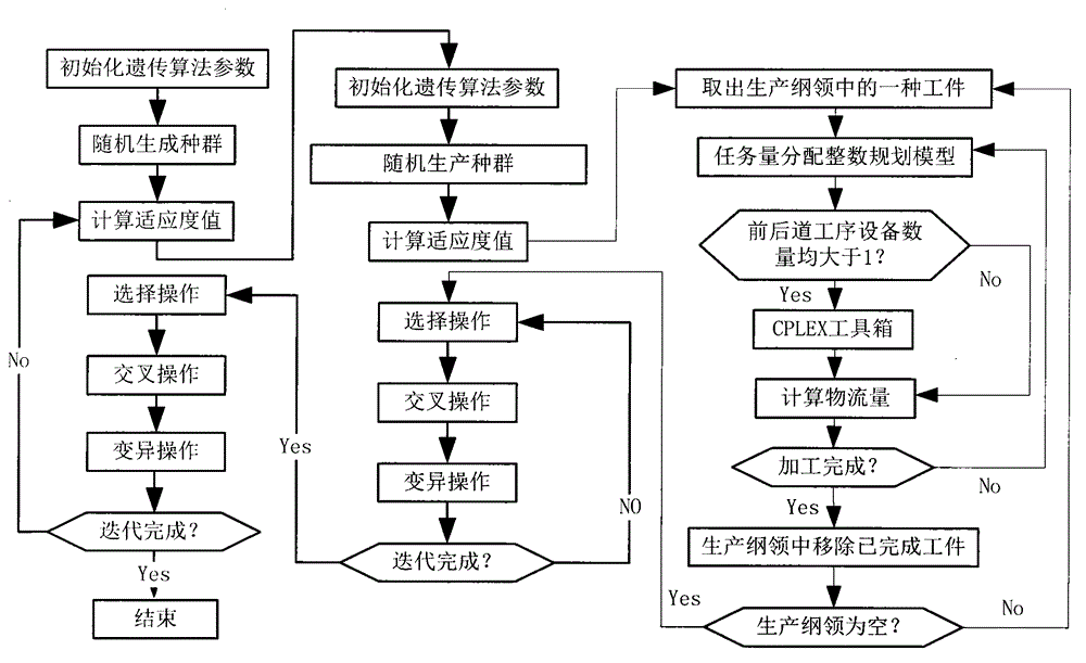
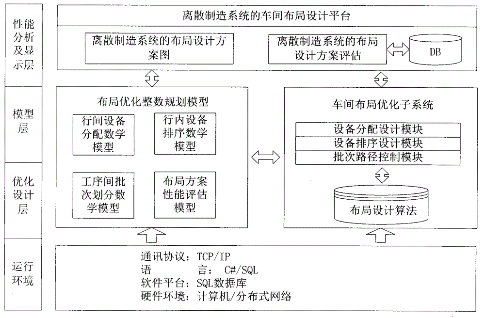
[0067] Specific examples figure 1 , figure 2 Shown, the realization steps of the present invention are as follows:

[0068] A. The UI layer of the system is used to input workshop equipment and production information to the layout design platform;

[0069] For example, workshop equipment and production information are shown in Tables 1, 2, and 3 respectively:

[0070] Table 1 Information table of workshop equipment

[0071] device ID

[0072] Table 2 Product order information table

[0073] product number

[0074] 5

[0075] Table 3 Product process information table

[0076]

[0077] B. Model building layer. According to the entered workshop information, build the mathematical model of inter-row equipment allocation, the mathematical model of intra-row equipment sorting, the mathematical model of batch division between processes, and the performance evaluation model of layout schemes;

[0078] C. Workshop layout optimization subsystem. ...


PUM


Abstract

The invention discloses a workshop layout method of a discrete manufacturing system. The workshop layout method comprises the specific steps: a system UI layer is used for recording workshop equipment and production information to a layout design platform; a model establishing layer is arranged; an inter-row equipment distribution mathematic model, an in-row equipment sorting mathematic model, an inter-procedure batch division mathematic model and a layout scheme performance estimation model are established respectively according to the recorded workshop information; a workshop layout optimization subsystem is arranged; a workshop layout design result estimation and display module is arranged. A user sends a layout design scheme to a server through module permission and workshop management staffs execute optimized results. The workshop layout method has the advantages that the defects that the workshop layout overall performance is reduced, caused by the fact that common layout optimization only considers block layout of a machining station, are avoided. Meanwhile, the optimal distribution of task amounts of an equipment workshop is considered under the condition that a plurality of sets of equipment of front and rear procedures are utilized, and the logistics transportation amount is further reduced by utilizing third-grade optimization.

Description

technical field [0001] The invention relates to a workshop layout method, in particular to a workshop layout method for a discrete manufacturing system. Background technique [0002] The workshop layout design of the discrete manufacturing system is one of the most critical and difficult design tasks in the manufacturing industry. The quality of its design directly affects the logistics cost and production efficiency of the production process, which has important theoretical significance and practical value. An effective layout optimization method can greatly improve the work efficiency of the enterprise, reduce the cost of logistics and transportation, enhance the competitiveness of the enterprise, and create considerable economic benefits. At the same time, the workshop layout optimization problem is a typical NP-hard problem, and an efficient layout design method can provide great convenience for factory designers and managers. [0003] The general discrete manufacturing...

Claims


Application Information

Patent Timeline
IPC IPC(8): G05B19/418
CPCG05B19/418G05B19/41805G05B2219/25314Y02P90/02
Inventor 李申范小斌秦威
Owner HAIAN COUNTY SHENLING ELECTRICAL APPLIANCE MFG
Learn More