
Energy conversion system, photovoltaic energy conversion system and method

An energy conversion system, photovoltaic technology, applied in the system field to achieve effective control

Active Publication Date: 2015-07-29
GENERAL ELECTRIC CO
View PDF4 Cites 2 Cited by
  • Summary
  • Abstract
  • Description
  • Claims
  • Application Information

AI Technical Summary

Problems solved by technology

However, the DC bus voltage control algorithms implemented in traditional power conversion systems still face considerable challenges when encountering transient events or grid faults.

Method used


Image

  • Energy conversion system, photovoltaic energy conversion system and method
  • Energy conversion system, photovoltaic energy conversion system and method
  • Energy conversion system, photovoltaic energy conversion system and method

Examples


Embodiment Construction

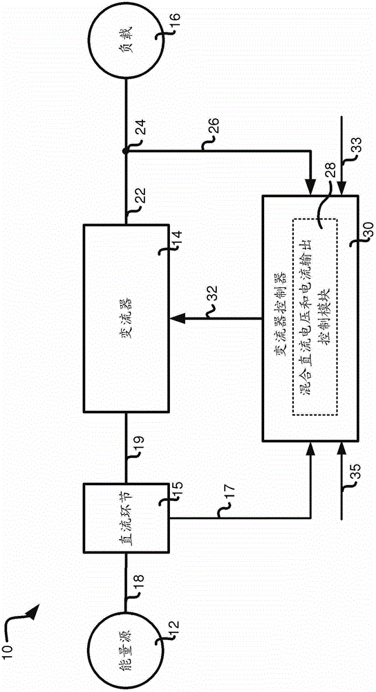
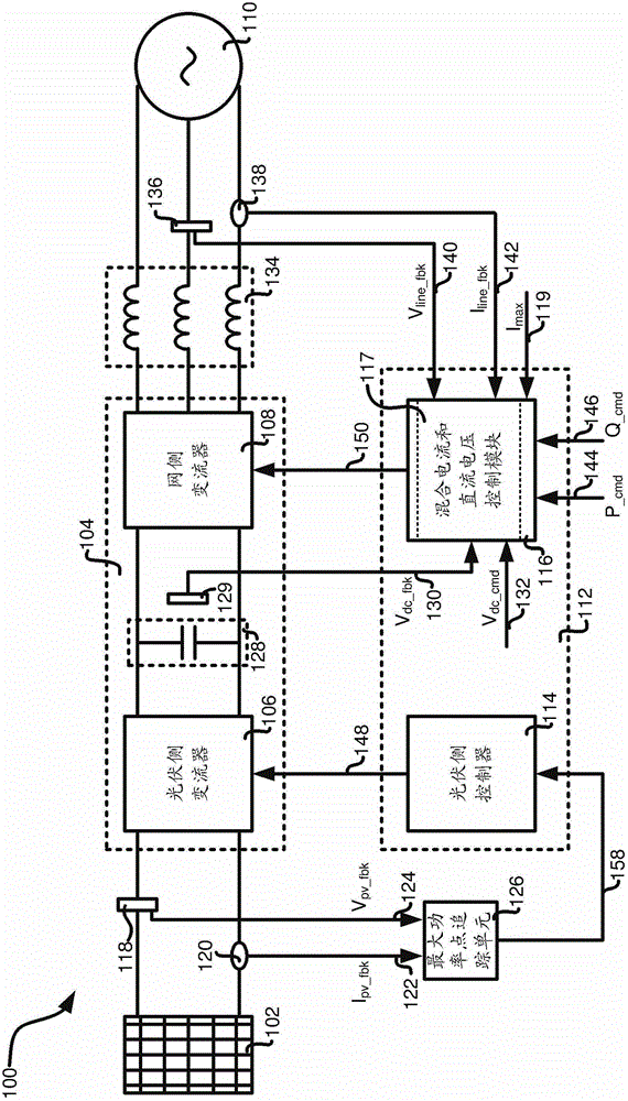
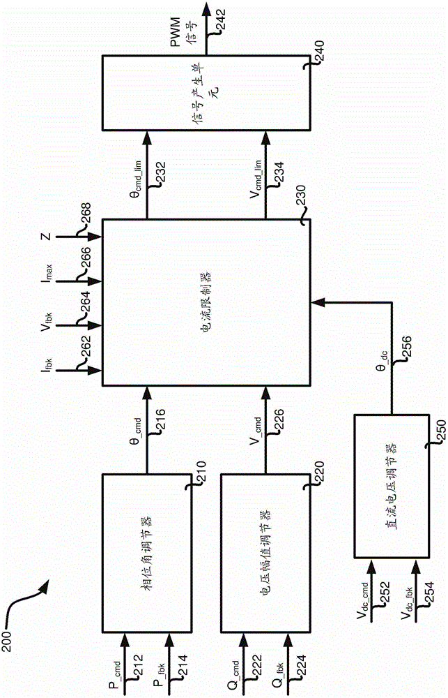
[0024] One or more embodiments disclosed in the present invention are related to energy conversion systems, or more specifically, energy generation systems or electric energy conversion systems, in particular, systems and methods for performing output current control and DC link voltage control in a coordinated manner. In some implementations, at least a part of the parameters related to the output current of the electric energy conversion system can be dynamically adjusted according to the adjustment requirements of the DC voltage of the DC link, so as to achieve coordinated control. For example, in some specific implementations, the phase angle limit signal used to limit the output current of the converter to cause overcurrent problems can be based on the DC voltage representing the actual DC link voltage deviating from the normal or expected DC link voltage. Link voltage deviation signal is dynamically adjusted. In some implementations, the phase angle limit signal can also...


PUM


Abstract

The invention relates to an energy conversion system, a photovoltaic energy conversion system and a method. The method comprises at least the following steps that: at least a maximum phase angle limiting signal and minimum phase angle limiting signal are generated at least based on current threshold values related to a converter device; a phase angle limiting adjustment signal is generated at least based on a direct current voltage instruction signal and an actual voltage signal related to the direct current link; the phase angle limiting adjustment signal is utilized to adjust at least one of the maximum phase angle limiting signal and the minimum phase angle limiting signal; and at least one of the maximum phase angle limiting signal and the minimum phase angle limiting signal is utilized to limit the phase angle instruction signal.

Description

technical field [0001] The embodiments disclosed in the present invention relate to systems and methods, and in particular to a system and method that can be used for coordinated control of output current and DC bus voltage. Background technique [0002] Energy conversion systems, including photovoltaic power generation devices, wind power generation devices, etc., are gradually being developed to replace traditional power generation devices, such as those based on fossil fuels. At least some known energy conversion systems are configured for grid connection, which can convert energy obtained from, for example, renewable energy sources, etc., into energy that meets grid requirements, such as having a specific voltage and frequency, etc. energy is fed into the grid. [0003] In order to enhance the control capability of the output current of the electric energy conversion system designed based on the voltage source model, a phase current control algorithm or control method h...

Claims


Application Information

Patent Timeline
IPC IPC(8): H02M7/42H02M1/32
CPCH02M7/42Y02E10/56
Inventor 侯丹邬心慧邬雪琴刘娇史经奎
Owner GENERAL ELECTRIC CO
Learn More