
Impurity separating equipment for soft sheet material

A technology of separation equipment and flakes, applied in the direction of solid separation, separation of solids from solids by air flow, chemical instruments and methods, etc., can solve problems such as low separation rate, air pollution, and limited centrifugal separation effect, and achieve improved separation efficiency, improve the separation effect

Active Publication Date: 2015-08-05
冯愚斌
View PDF11 Cites 3 Cited by
  • Summary
  • Abstract
  • Description
  • Claims
  • Application Information

AI Technical Summary

Problems solved by technology

This waste plastic film recycling separator has the following deficiencies: 1. During the air delivery process, some impurities are bonded together with the plastic film, and it is difficult to separate them at one time. 2. Due to the limited number of heavy object separation ports and light object separation ports, and the density of impurities mixed in the plastic film is different, it is difficult to make all the impurities from the heavy object 3. The gas used to blow the plastic film is directly discharged into the air. Since the plastic film to be treated will be mixed with some harmful gases, these gases and the blown plastic The gas of the film is directly discharged into the air, which will cause air pollution
This waste plastic film impurity separator separates the plastic film and impurities through centrifugal action, and the impurities can fall from the sieve holes during the process of conveying in the separation cylinder, but there are the following disadvantages: the effect of centrifugal separation is limited, usually only for The loose plastic film and impurities are separated, and it is difficult to separate the plastic film and impurities that are formed into agglomerates; moreover, the separation cylinder needs to be filled with the materials to be processed during the working process of the waste plastic film impurity separator, otherwise the materials cannot be conveyed forward , and too much to be treated piles up together, not only is not conducive to the separation of impurities and plastic films, but also the separated impurities are difficult to completely transfer to the separation cylinder and drop, and the separation effect is still not good

Method used


Image

  • Impurity separating equipment for soft sheet material
  • Impurity separating equipment for soft sheet material
  • Impurity separating equipment for soft sheet material

Examples


Embodiment 1

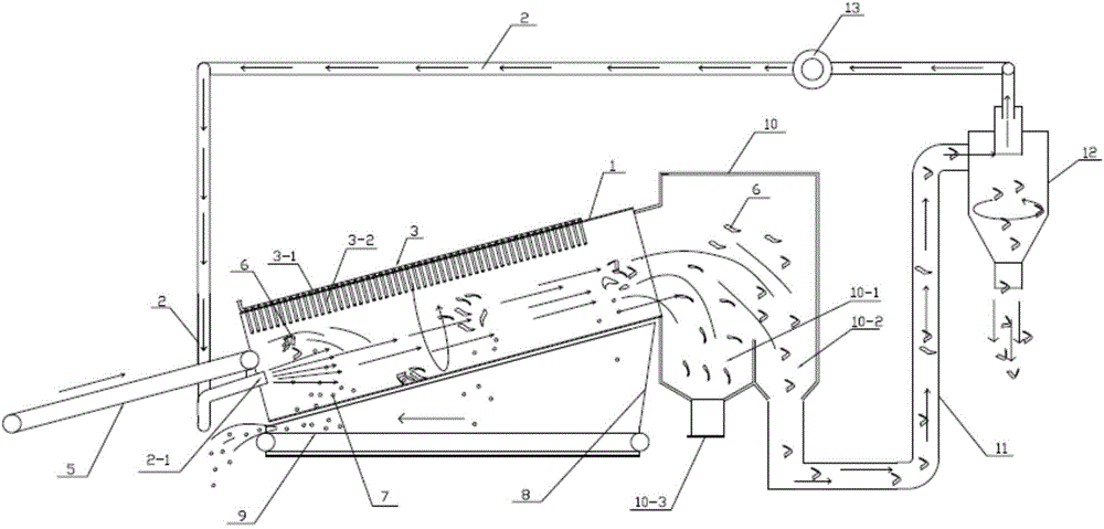
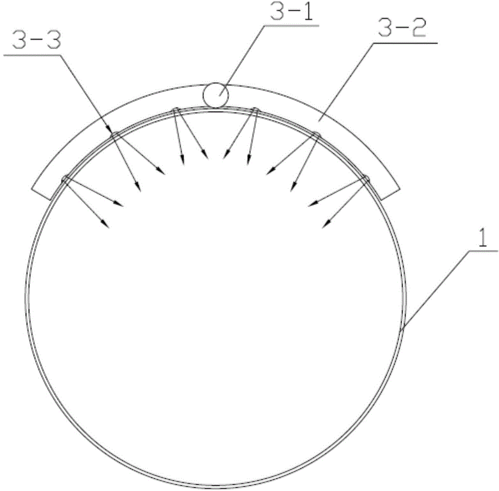
[0049] see figure 1 , The impurity separation equipment for soft flake materials in this embodiment includes an air supply device, a separation cylinder 1, a separation cylinder driving device for driving the separation cylinder 1 to rotate, a feeding mechanism, a secondary separation device for soft flakes, and a gas separation device for soft flakes. Wherein, the air supply device includes a fan and an air duct 2 connected with the fan. The wall of the separating cylinder 1 is provided with screen holes, and the two ends of the separating cylinder 1 are open, wherein the opening at one end is the feeding end, and the opening at the other end is the discharging end; the air outlet of the air duct 2 2-1 is set at the feeding end of the separation cylinder 1. The driving device of the separation cylinder 1 is composed of a ring gear arranged on the outer wall of the separation cylinder 1, a driving gear meshed with the ring gear and a motor connected with the driving gear. Th...

Embodiment 2

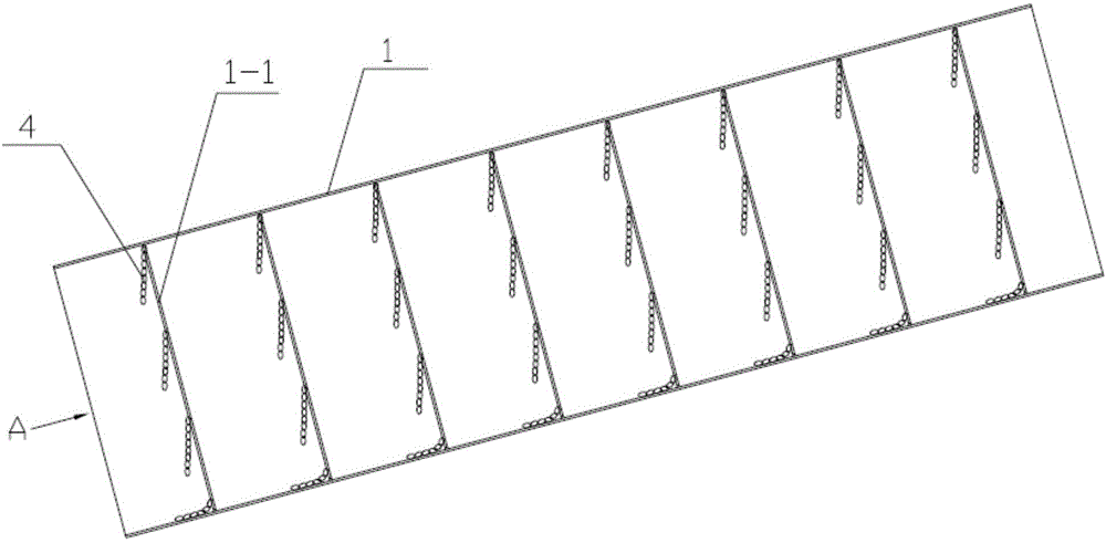
[0060] See 3~ Figure 5 In this embodiment, a hanging chain 4 is installed in the inner wall of the separation cylinder 1 to replace the pulse air flow device 3 in the embodiment 1, so as to prevent the clogging of the screen holes and improve the separation effect. The chains 4 provided on the inner wall of the separation cylinder 1 are multiple groups, the chains 4 are metal chains, and the multiple groups of chains 4 are distributed along the axial direction of the separation cylinder 1, and each group of chains 4 includes A plurality of hanging chains 4 distributed in the circumferential direction. Its working principle is: when the separation cylinder 1 is in a static state, the hanging chain 4 located at the upper part of the separation cylinder 1 hangs down naturally, and the hanging chain 4 at the bottom of the separation cylinder 1 lies on the separation cylinder 1; the separation cylinder 1 continuously Rotation, in the process of the separation drum 1 rotating one ...

Embodiment 3

[0065] see Figure 6 , In this embodiment, the pulse air flow device 3 in embodiment 1 and the chain 4 in embodiment 2 are used at the same time to better prevent the clogging of the screen hole and improve the separation effect.

[0066] Embodiments other than the above in this embodiment are the same as in Embodiment 1.


PUM


Abstract

The invention discloses impurity separating equipment for soft sheet material. The impurity separating equipment comprises an air supply device, a separating barrel, a separating barrel drive device, a feeding mechanism, a secondary soft sheet separating device and a soft sheet gas separating device, wherein the air supply device comprises a fan and an air pipe connected with the fan; sieve holes are formed in the wall of the separating barrel, and two ends of the separating barrel are opened; the secondary soft sheet separating device comprises a separating box connected with the discharge end of the separating barrel, and a high-density soft sheet gathering box and a small-density soft sheet gathering box are arranged in the separating box; the soft sheet gas separating device comprises a cyclone separator, the feed hole of the cyclone separator is connected with the bottom of the small-density soft sheet gathering box, and the top exhaust hole is connected with an air pipe in the air supply device. The impurity separating equipment has advantages of good impurity separating effect and high separating rate, and moreover, the separated soft sheet material can be classified, and the gas can be separated from the separated soft sheet material to recycle.

Description

technical field [0001] The invention relates to a production line for material recovery and processing, in particular to an impurity separation device for soft and flake materials. Background technique [0002] Materials with soft characteristics (such as cloth, paper, plastic film, etc.) are widely used in daily life and production. If these materials are recycled after use, it is necessary to remove impurities entrained in the use and collection process to obtain clean Gentle flake material. [0003] Soft flake materials are soft, easy to curl into agglomerates, or have adhesive properties, making it difficult to separate the trapped impurities. For example, in the agricultural plastic film, the used plastic film is usually mixed with impurities such as soil, sand, and plant debris, especially plant debris, whose density is almost the same as that of the plastic film. It is difficult for the separation device of the prior art to achieve separation Effect. [0004] For e...

Claims


Application Information

Patent Timeline
IPC IPC(8): B07B7/01B07B7/083B07B7/12B07B11/06
Inventor 冯愚斌
Owner 冯愚斌
Learn More