Anti-liquefaction three-dimensional drainage rigid pile and construction method thereof
A rigid pile, anti-liquefaction technology, applied in sheet pile wall, foundation structure engineering, construction, etc., can solve the problems of house damage, unusable foundation, rigid pile foundation damage, etc., to increase construction cost, technical operation convenience, use simple effect
- Summary
- Abstract
- Description
- Claims
- Application Information
AI Technical Summary
Problems solved by technology
Method used
Image
Examples
Embodiment 1
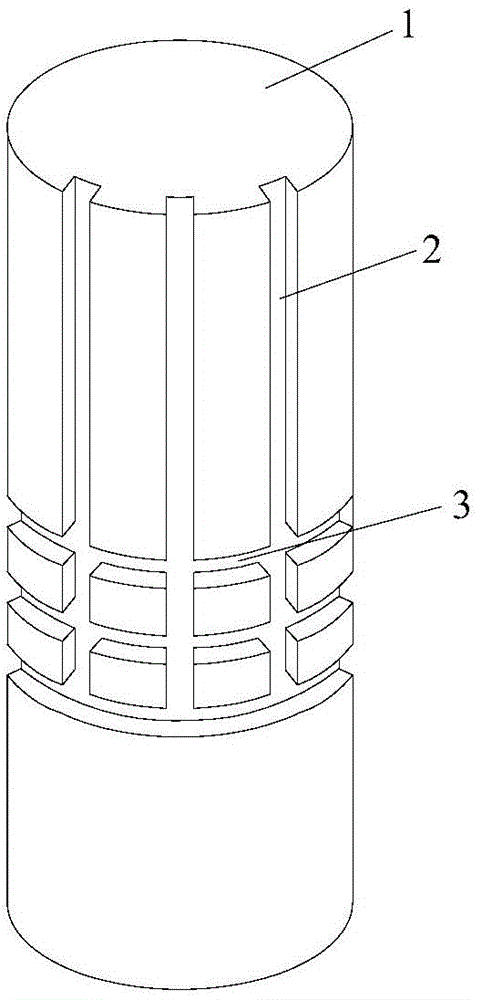
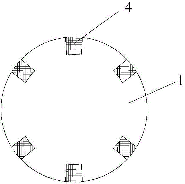
[0026] see figure 2 , the rigid pile 1 is a reinforced concrete prefabricated pile. During prefabrication, a vertical drainage groove 2 and a horizontal drainage groove 3 are arranged on its side. figure 2 The reinforced concrete prefabricated pile is a cylinder, and several (three) horizontal drainage grooves 3 surround the side walls of the reinforced concrete prefabricated pile. These horizontal drainage grooves 3 are respectively on a plane parallel to the bottom surface of the cylinder. Such as image 3 , a number of (six) vertical drainage grooves 2 are evenly distributed on the side wall of the cylinder, these vertical drainage grooves 2 are all parallel to the axial direction of the cylinder, and their upper ends are at the top and lower end of the cylinder and each horizontal row The sinks 3 are connected.
[0027] Vertical drainage body 4 and horizontal drainage body 5 are respectively placed in vertical drainage groove 2 and horizontal drainage groove 3, and the...
Embodiment 2
[0030] Present embodiment is a construction process of the pile body of embodiment 1:
[0031] During construction, the engineering geological survey of the construction site shall be carried out first to determine the distribution position and depth of the liquefiable soil layer.
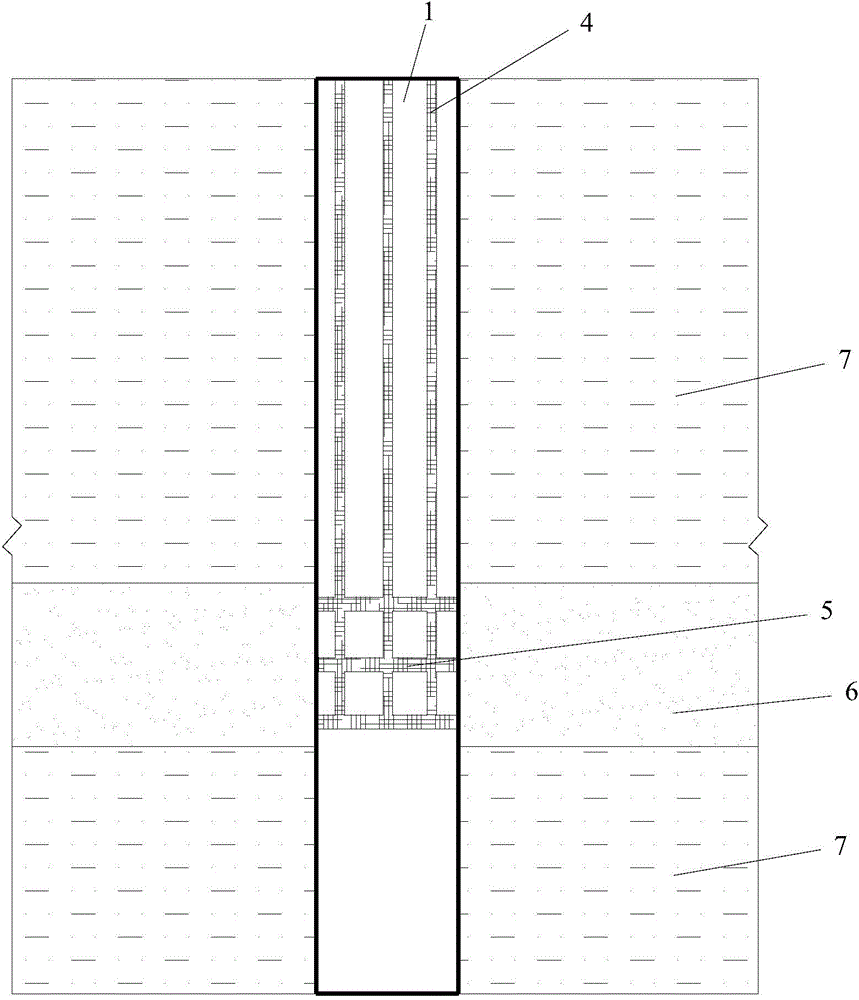
[0032] In the next step, the rigid pile 1 as in embodiment 1 is prefabricated in a factory. During prefabrication, the positions of the vertical drainage groove 2 and the horizontal drainage groove 3 are reserved first, and corresponding grooves are formed after the concrete is poured and formed. see figure 1 , the position of the groove is determined according to the geological survey report in the previous step, so that the bottom of the vertical drainage channel 2 reaches the bottom of the liquefiable soil layer 6, and the horizontal drainage channel 3 is located in the liquefiable soil layer 6, while the non-liquefiable soil layer 7 is not set Horizontal gutter 3.
[0033] In the next step, ...
PUM
 Abstract
Description
Claims
Application Information
 - R&D
- Intellectual Property
- Life Sciences
- Materials
- Tech Scout
- Unparalleled Data Quality
- Higher Quality Content
- 60% Fewer Hallucinations
Browse by: Latest US Patents, China's latest patents, Technical Efficacy Thesaurus, Application Domain, Technology Topic, Popular Technical Reports.
© 2025 PatSnap. All rights reserved.Legal|Privacy policy|Modern Slavery Act Transparency Statement|Sitemap|About US| Contact US: help@patsnap.com


