Turbine rear support bearing seat, cooling method and turbine fan engine

A turbo fan and bearing seat technology, which is applied to engine components, machines/engines, mechanical equipment, etc., can solve the problems of uneven cooling air, decreased performance of the whole machine, and increased self-weight of the whole machine, and achieves high cooling efficiency and weight reduction. , the effect of improving structural performance

Active Publication Date: 2015-08-05
CHINA AVIATION POWER MACHINE INST
View PDF7 Cites 14 Cited by
  • Summary
  • Abstract
  • Description
  • Claims
  • Application Information

AI Technical Summary

Problems solved by technology

[0007] The invention provides a turbine rear support bearing seat, a cooling method and a turbofan engine to solve the existing cooling method for the rear bearing of the low-pressure turbine rotor. Since the cooling of the bearing seat is carried out by the bleed air from the compressor, the performance of the whole machine may be easily reduced. and the cooling effect is poor; the cooling of the bearing seat is carried out through the external pipeline, which has a complex structure and is likely to increase the weight of the whole machine, while too little external pipeline air intake is likely to cause uneven cooling air and lower cooling efficiency. low technical issues

Method used


Image

  • Turbine rear support bearing seat, cooling method and turbine fan engine
  • Turbine rear support bearing seat, cooling method and turbine fan engine

Examples


Embodiment Construction

[0026] The embodiments of the present invention will be described in detail below with reference to the accompanying drawings, but the present invention can be implemented in various ways defined and covered.

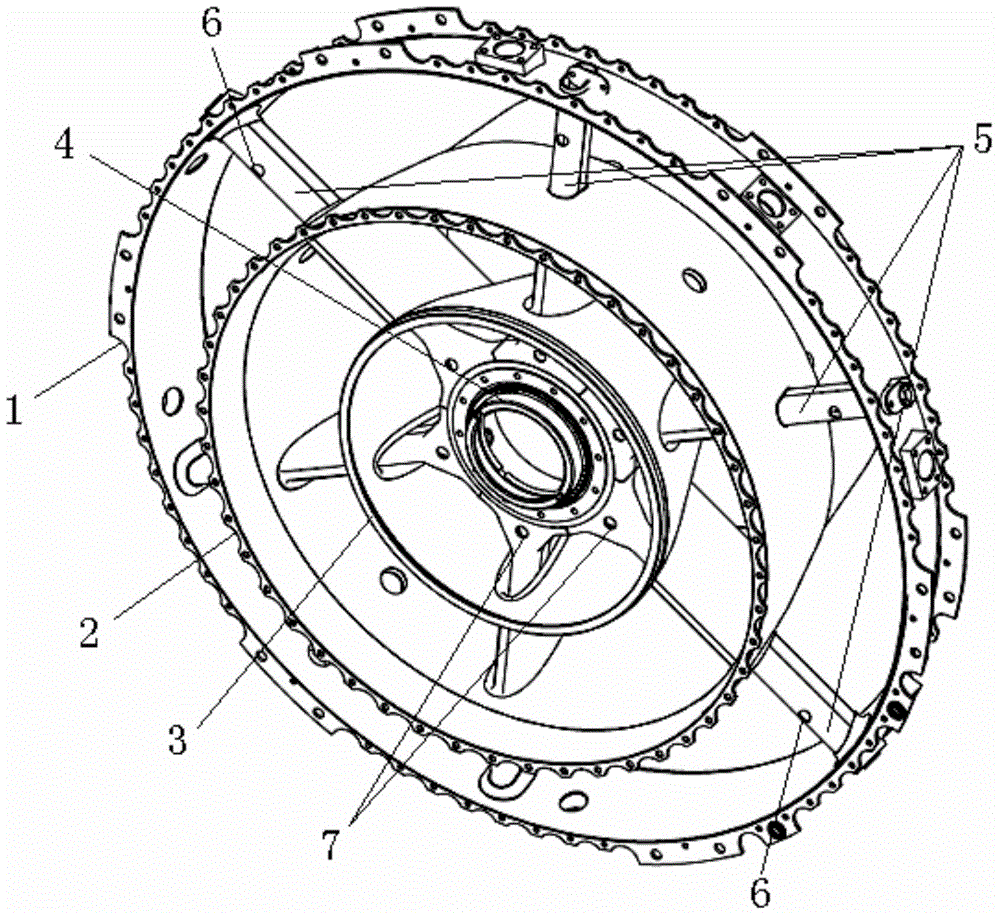
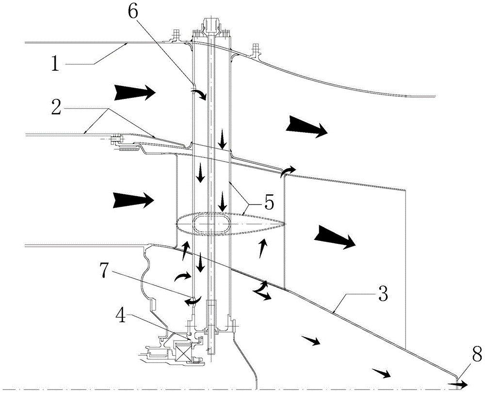
[0027] figure 1 It is a structural schematic diagram of the turbofan engine turbine rear support bearing seat in a preferred embodiment of the present invention; figure 2 It is a schematic diagram of the fluid flow direction of the turbo fan engine turbine rear support bearing seat of the preferred embodiment of the present invention.

[0028] Such as figure 1 As shown, the turbofan engine turbine rear support bearing seat of this embodiment includes an outer casing 1, a main flow casing 2, an exhaust casing 3 and a bearing seat 4, and the outer casing 1 and the main flow casing 2 The outer duct is formed between the main channel casing 2 and the exhaust casing 3 to form an inner passage, the exhaust casing 3 forms a bearing cavity, and the outer wall of the bearing ...


PUM


Abstract

The invention discloses a turbine rear support bearing seat, a cooling method and a turbine fan engine. The turbine rear support bearing seat of the turbine fan engine comprises an outer containing cartridge receiver, a main runner cartridge receiver, a gas exhauster cartridge receiver and a bearing seat, wherein an outer duct is formed between the outer containing cartridge receiver and the main runner cartridge receiver; an inner duct is formed between the main runner cartridge receiver and the gas exhauster cartridge receiver; a bearing cavity is formed in the gas exhauster cartridge receiver, and a bearing support plate used for guiding the outer containing cold liquid in the outer duct to the bearing seat for exchanging heat for cooling the bearing seat is arranged on the outer wall surface of the bearing seat. The bearing support plate is used for supporting the fluid flow passage, offering the liquid cooling loop for cooling rear support bearing seat, cooling and protecting the oil inlet pipeline and the oil returning pipeline of the oil and improving the structure performance of the complete machine.

Description

technical field [0001] The invention relates to the field of cooling of turbofan engine bearings, in particular to a turbofan engine turbine rear support bearing seat. In addition, the present invention also relates to a turbofan engine comprising the above-mentioned turbine rear support bearing seat and a cooling method for the above-mentioned turbine rear support bearing seat. Background technique [0002] For gas turbine engines with double (three) rotors, especially in turbofan engines, the structure scheme of rear support is widely used in the low-pressure turbine. [0003] The rear bearing of the low-pressure turbine rotor is installed on the bearing seat inside the rear support casing. Due to the high-speed rotation of aviation bearings, a large amount of frictional heat will be generated, and due to the characteristics of gas turbine engines, the entire bearing cavity is surrounded by an annular gas channel, and the high-temperature gas temperature in the gas channe...

Claims


Application Information

Patent Timeline
Patent Type & Authority Applications(China)
IPC IPC(8): F01D25/16F01D25/12
Inventor 陶冶科陈竞炜李鑫付晟白忠恺叶炜
Owner CHINA AVIATION POWER MACHINE INST
Why Eureka
Try Eureka