Device and method for automatically scanning test tube bar code

An automatic scanning and test tube technology, applied in the direction of electromagnetic radiation induction, etc., can solve the problem of inability to automatically scan test tube barcodes in batches, and achieve the effect of convenient scanning of test tube barcodes, simple and convenient operation, and not easy to damage.

Active Publication Date: 2015-08-05
GENRUI BIOTECH INC
View PDF5 Cites 25 Cited by
  • Summary
  • Abstract
  • Description
  • Claims
  • Application Information

AI Technical Summary

Problems solved by technology

When working, the motor drives the main rotating arm 53 and the auxiliary rotating arm 54 to clamp the test tube 51 or release the test tube 51. When the test tube 51 is clamped, the photoelectric switch senses that the main rotating arm 53 ro

Method used


Image

  • Device and method for automatically scanning test tube bar code
  • Device and method for automatically scanning test tube bar code
  • Device and method for automatically scanning test tube bar code

Examples


Embodiment 1

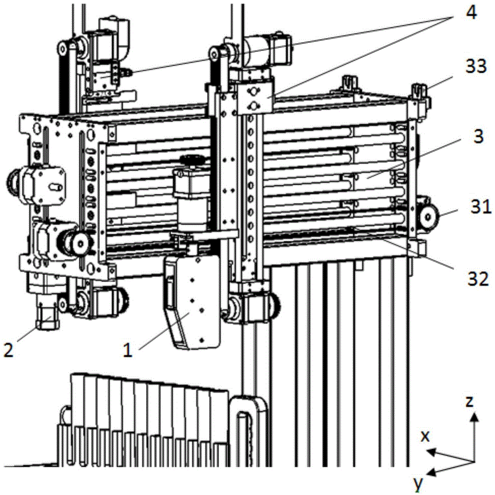
[0054] Such as figure 2 As shown, an automatic scanning device for test tube barcodes includes a scanning device 1, a tube revolving device 2, and an equipment main body. The main body of the equipment includes a first driving device that drives the tube revolving device 2 to move in the vertical direction, that is, Z-direction motion, and a driving tube revolving device 2 The second driving device that moves in the horizontal direction is the Y-direction movement.

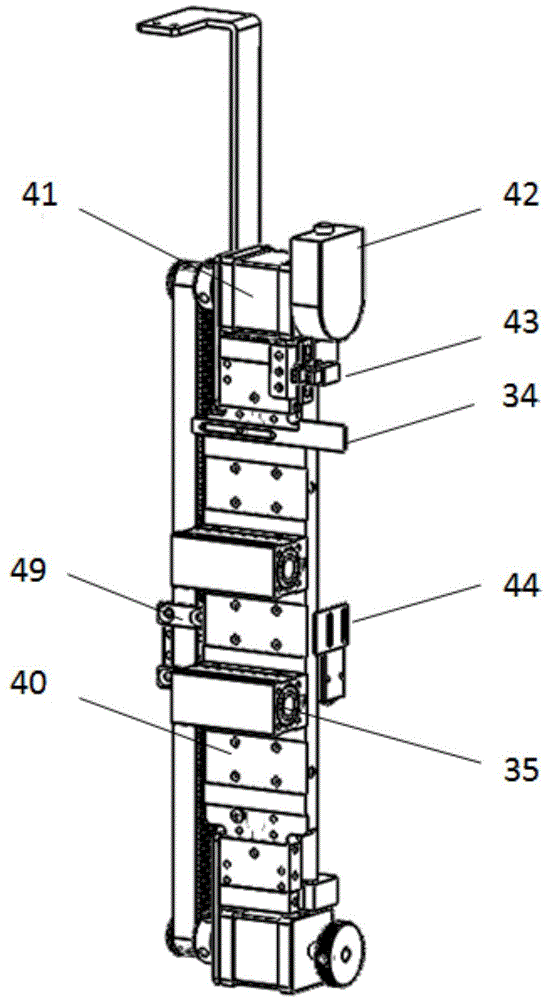
[0055] Such as figure 2 , image 3 , Figure 4 As shown, the first driving device includes a Z-direction bracket 4 installed on the main body of the equipment, which includes a Z-direction bracket body 40, a Z-direction drive motor 41, and a positioning unit 42 mounted on the motor shaft such as an encoder and a Z-direction positioning device 43, Z-direction reset baffle 44, motor mounting frame 45, lifting rail seat 46, Z-direction optical axis guide 47, Z-direction slider 48 containing linear bearings, belt pressi...

Embodiment 2

[0066] On the basis of the first embodiment, the equipment is provided with a third driving device for vertical movement and a fourth driving device for horizontal movement similar to the first driving device and the second driving device. Different carriers are designed on the Z-direction slider 48 on the first driving device and the third driving device according to requirements, and suitable motors are selected according to the load. The scanning device 1 and the rotating tube device 2 are both carrier mechanisms on the Z-direction bracket 4.

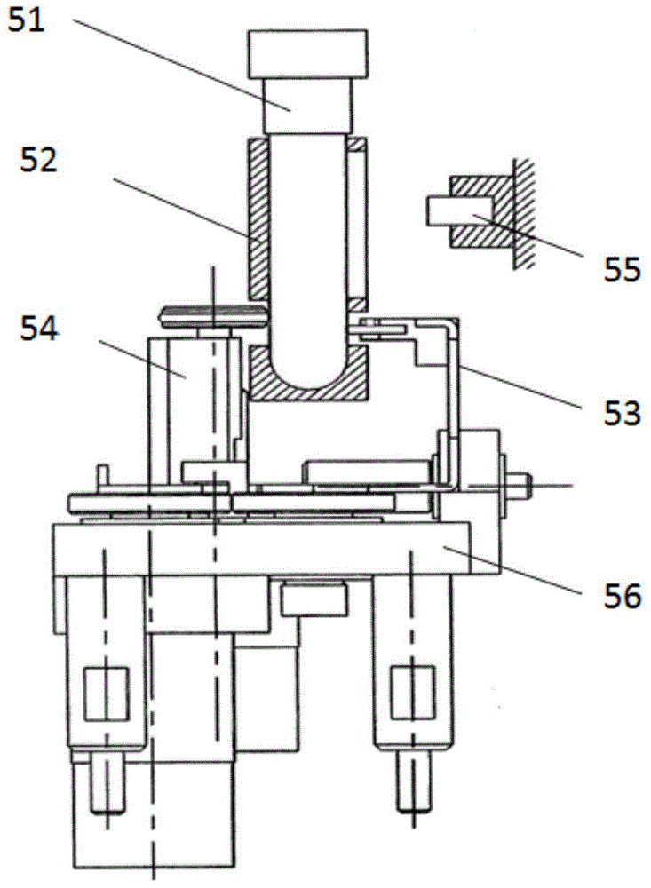
[0067] Such as figure 2 , Figure 5 with Image 6 As shown, the scanning device 1 includes a bar code gun mounting frame 10, a bar code gun drive motor 11 such as a planetary reduction stepper motor, a rotating motor seat 12, a bar code gun box 13, a bar code gun positioning plate 14, and a bar code gun positioning device 15. The bar code gun box includes a bar code gun shaft 16, a detection unit 17 for detecting a test tube, such as a ...

Embodiment 3

[0070] Such as Figure 15 As shown, a method for scanning the barcode of a test tube, using the device of Embodiment 1 or Embodiment 2, includes the following steps:

[0071] S1: The detection unit detects the target test tube; if the test tube is detected, the scanning device scans the test tube;

[0072] S2: If the barcode is not scanned, the tube rotating device picks up the upper part of the target test tube through the tube clamp, moves the target test tube horizontally and vertically into the position to be scanned, and rotates the target test tube for the scanning device to scan the target test tube After scanning the barcode on the test tube, the tube stripping device returns the test tube to its original position.

[0073] Preparatory work before scanning the test tube barcode: Before the test tube rack is ready to enter the detection channel, the Y-direction drive motor 31 is driven by the timing belt, and the Z-direction bracket 4 where the scanning device 1 is located is ...


PUM


Abstract

The invention discloses a device and a method for automatically scanning test tube bar codes. The device comprises a scanning device used for scanning the test tube bar codes, a tube rotation device used to pick up a test tube and rotate the test tube, a first drive device which is connected with the tube rotation device and drives the tube rotation device to do vertical motion on a main body of the device, and a second drive device which is connected with the tube rotation device and drives the tube rotation device to do horizontal motion on the main body of the device. The tube rotation device comprises a tube clamp which picks up the upper part of a test tube, a tube rotation driver which drives the tube clamp to rotate, and a tube separating mechanism which makes the test tube separate from the tube clamp. The device can realize production line type operation for test tube bar code scanning, and in test tube feeding, the device is not limited in single-channel production line operation, and at least two rows of test tubes are fed in, thereby improving working efficiency. The device is simple in design, compact in structure, and small in appearance, and saves space.

Description

Technical field [0001] The invention relates to the field of medical in vitro diagnostic equipment, and more specifically, to an automatic scanning device and method for test tube barcodes. Background technique [0002] Barcode technology uses a bar code to represent the data required by the computer, and then converts the bar code data into data that the computer can automatically read. With the modernization and automation of inspection instruments, most inspection instruments have bar code reading capabilities. As the unique identification of the specimen, the barcode is applied to the entire analysis process of the specimen, standardizes the work flow, and facilitates doctors and patients to obtain relevant information. The application of barcode technology in the medical laboratory information network system can improve the level of medical management, optimize the inspection and management process, improve work efficiency, and minimize medical errors. It also protects the ...

Claims


Application Information

Patent Timeline
IPC IPC(8): G06K7/10
Inventor 冯尧胡津
Owner GENRUI BIOTECH INC
Why Eureka
Try Eureka