Inductively coupled plasma reactor

A plasma and reactor technology, applied in the direction of circuits, discharge tubes, electrical components, etc., can solve the problems of increasing the distance between the radio frequency antenna and the plasma, reducing the power transfer effect, etc., to achieve suppressed losses, easy and correct adjustment, and uniform substrates processing effect

Active Publication Date: 2015-08-05
UNKNOWN +1
View PDF6 Cites 9 Cited by
  • Summary
  • Abstract
  • Description
  • Claims
  • Application Information

AI Technical Summary

Problems solved by technology

In addition, when high power is applied to the antenna, the capacitive coupling of the RF antenna increases, so that the dielectric window must be thickened, thereby causing the distance between the RF antenna and the plasma to increase, resulting in a reduced power transfer effect. question

Method used


Image

  • Inductively coupled plasma reactor
  • Inductively coupled plasma reactor
  • Inductively coupled plasma reactor

Examples


Embodiment Construction

[0050] Hereinafter, the plasma reactor of the present invention will be described in detail by explaining preferred embodiments of the present invention with reference to the accompanying drawings. The embodiments of the present invention can be modified in various ways, and the scope of the present invention is not limited to the following embodiments. This embodiment is provided to describe the present invention more completely for those skilled in the art. Therefore, for clearer description, the shapes of components and the like in the drawings are exaggerated. In order to facilitate understanding of the drawings, the same reference numerals are assigned to the same components as much as possible. In addition, detailed technical descriptions are omitted for known functions and structures that are judged to obscure the gist of the present invention.

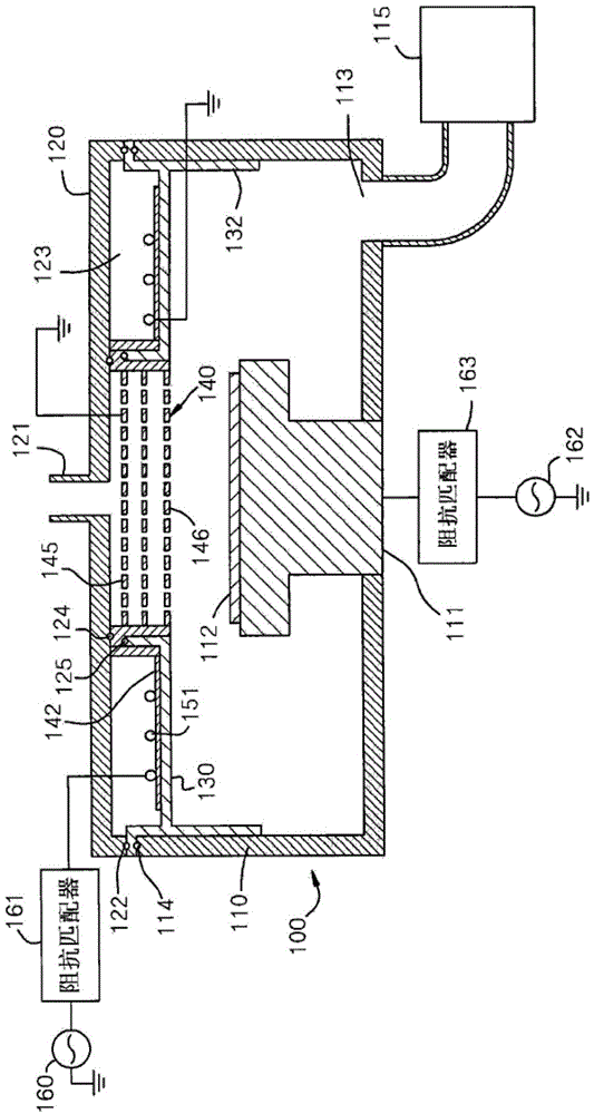
[0051] figure 1 is a sectional view of the plasma reactor according to the first embodiment of the present invention.

[...


PUM


Abstract

There is provided a plasma reactor comprising: a vacuum chamber (100) having a substrate support (111) on which a treated substrate (112) is positioned; a gas shower head (140) supplying gas into the interior of the vacuum chamber; a dielectric window (130) installed at an upper portion of the vacuum chamber; and a radio frequency antenna (151) installed above the dielectric window. The gas shower head and the substrate support are capacitively coupled to plasma in the interior of the vacuum chamber and the radio frequency antenna is inductively coupled to the plasma in the interior of the vacuum chamber. The capacitive and inductive coupling of the plasma reactor allows generation of plasma in a large area inside the vacuum chamber more uniformly and more accurate control of plasma ion energy, thereby increasing the yield and the productivity. The plasma reactor includes a magnetic core (150) installed above the dielectric window so that an entrance for a magnetic flux faces the interior of the vacuum chamber and covers the radio frequency antenna. Since the radio frequency antenna is covered by the magnetic core, the magnetic flux can be more strongly collected and the loss of the magnetic flux can be minimized.

Description

[0001] This application is a divisional application of the patent application whose filing date is May 22, 2007, application number is 200710105100.0, and the invention title is "Inductively Coupled Plasma Reactor". technical field [0002] The present invention relates to a radio frequency (radio frequency) plasma source (plasma source), in particular to an inductively coupled plasma reactor capable of generating high-density plasma more uniformly. Background technique [0003] A plasma is a highly ionized gas containing equal numbers of positive ions and electrons. Plasma discharge is used for gas excitation to generate reactive gases including ions, radicals, atoms, molecules. Reactive gases are widely used in various fields, and are typically used in semiconductor manufacturing processes such as etching, deposition, cleaning, ashing, and the like. [0004] There are various plasma sources for generating plasma, but typical examples thereof include capacitive coupled pla...

Claims


Application Information

Patent Timeline
Patent Type & Authority Applications(China)
IPC IPC(8): H01J37/32
CPCH01J37/3266H01J37/32165H01J37/32449H01J37/32146H01J37/32119H01J37/32082H01J37/3211H01J37/321H01J37/32128H01J37/32174H01J37/32155H01J37/32091H01J37/32183H01J37/32137
Inventor 崔大圭
Owner UNKNOWN
Why Eureka
Try Eureka