Continuous stacking equipment for storage battery grids
A battery and grid technology, which is applied in the field of battery grid continuous stacking equipment, can solve problems such as inability to meet production requirements, and achieve the effects of compact structure, improved production efficiency and simple operation.
- Summary
- Abstract
- Description
- Claims
- Application Information
AI Technical Summary
Problems solved by technology
Method used
Image
Examples
Embodiment 1
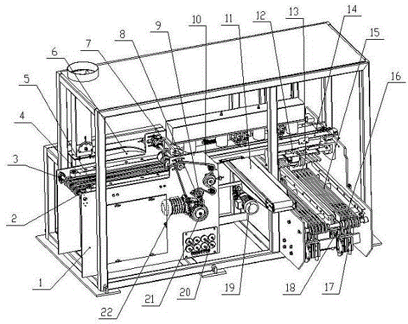
[0025] In order to overcome that the existing grid stacking equipment cannot meet the requirements of rapid grid production, this embodiment provides a method such as figure 1 The battery grid continuous stacking equipment shown includes a frame 1 and a sheet feeding mechanism 2 fixed on the frame 1, a vacuum conveying mechanism 7, a driving mechanism 8, a waste sheet recycling mechanism 11, a falling sheet guiding mechanism 12, a receiving mechanism Sheet mechanism 13 and stacking mechanism 15; described sheet advancing mechanism 2 and vacuum conveying mechanism 7 are all connected with driving mechanism 8 transmission, and the transmission direction of described sheet advancing mechanism 2 and vacuum conveying mechanism 7 are consistent, and vacuum conveying mechanism 7 and advancing The sheet mechanism 2 has an overlapping amount greater than twice the grid width in the horizontal direction and a gap of twice the grid thickness in the vertical direction. The waste sheet reco...
Embodiment 2
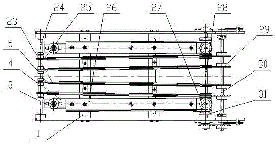
[0029] On the basis of Example 1, such as figure 2 As shown, the film advance mechanism 2 includes a small pulley 3, a belt 4, a film advance chain 5, a guide rail 23, a driven shaft 24, a small sprocket 25, a guide plate 26, a large pulley 27, a belt drive shaft 28, Large sprocket 29, chain drive shaft 30 and steering box 31; The two ends of driven shaft 24, belt drive shaft 28 and chain drive shaft 30 are all fixed on the frame 1, and a plurality of small Sprocket 25, on the chain drive shaft 30, connect a plurality of large sprockets 29 by key, small sprocket 25 and large sprocket 29 are connected by the sheet-advancing chain 5 one-to-one correspondingly by guide rail 23 pair of sheet-advancing chain 5 guides simultaneously, carry out The sheet chain 5 is symmetrically arranged at 3 to 5°, the small pulley 3 and the large pulley 27 are respectively arranged on the outer sides of the two ends of the sheet feeding chain 5, the small pulley 3 and the large pulley 27 are conne...
Embodiment 3
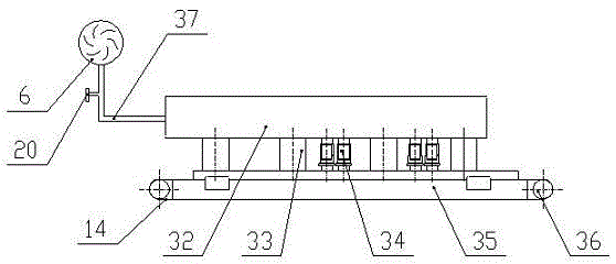
[0032] On the basis of Example 1, such as figure 1 and image 3 As shown, the vacuum transfer mechanism 7 includes a blower fan 6, an air valve 20, a vacuum belt 14, a vacuum box 32, a ventilation column 33, an air shut-off valve 34, a vacuum distribution box 35, a pulley 36 and a pipeline 37; the blower fan 6 and the vacuum box 32 pass through The pipeline 37 is connected, the air valve 20 is fixed on the pipeline 37, the vacuum box 32 and the vacuum distribution box 35 are placed side by side up and down, the ventilation column 33 and the air shut-off valve 34 connect the vacuum box 32 and the vacuum distribution box 35 as a whole, and the pulley 36 is set in the vacuum At both ends of the distribution box 35, the vacuum belt 14 is stretched around the pulley 36 and then attached to the bottom air inlet of the vacuum distribution box 35. The vacuum belt 14 is evenly distributed with ventilation holes, and the vacuum distribution box 35 is fixed symmetrically along the direct...
PUM
 Abstract
Description
Claims
Application Information
 - R&D
- Intellectual Property
- Life Sciences
- Materials
- Tech Scout
- Unparalleled Data Quality
- Higher Quality Content
- 60% Fewer Hallucinations
Browse by: Latest US Patents, China's latest patents, Technical Efficacy Thesaurus, Application Domain, Technology Topic, Popular Technical Reports.
© 2025 PatSnap. All rights reserved.Legal|Privacy policy|Modern Slavery Act Transparency Statement|Sitemap|About US| Contact US: help@patsnap.com


