An automatic feeding mechanism used for quenching of shaft type workpieces

A shaft workpiece, automatic feeding technology, applied in the direction of quenching device, furnace type, manufacturing tools, etc., can solve the problems affecting the mechanical properties of the motor mandrel, affecting the straightness of the motor mandrel, and the damage to the structure of the motor mandrel, so as to avoid Minor bending deformation, high level of automation, and the effect of improving quenching quality

Active Publication Date: 2015-08-12
NINGBO HAWK ELECTRICAL APPLIANCE CO LTD
View PDF5 Cites 7 Cited by
  • Summary
  • Abstract
  • Description
  • Claims
  • Application Information

AI Technical Summary

Problems solved by technology

However, in the process of quenching the motor mandrel by this kind of quenching machine, there is a certain distance between the heating and cooling areas. When the heated motor mandrel is transported on the conveyor belt, the heat at both ends of the motor mandrel will be transferred to the motor mandrel. The inside of the shaft causes the inside of the motor shaft to be cooked, causing damage to the internal structure of the motor shaft and affecting the mechanical properties of the motor shaft
In addition, erecting the motor mandrel on the conveyor belt may easily cause slight bending of the motor mandrel, which affects the straightness of the motor mandrel

Method used


Image

  • An automatic feeding mechanism used for quenching of shaft type workpieces
  • An automatic feeding mechanism used for quenching of shaft type workpieces
  • An automatic feeding mechanism used for quenching of shaft type workpieces

Examples


Embodiment Construction

[0024] The present invention will be further described in detail below in conjunction with the accompanying drawings and embodiments.

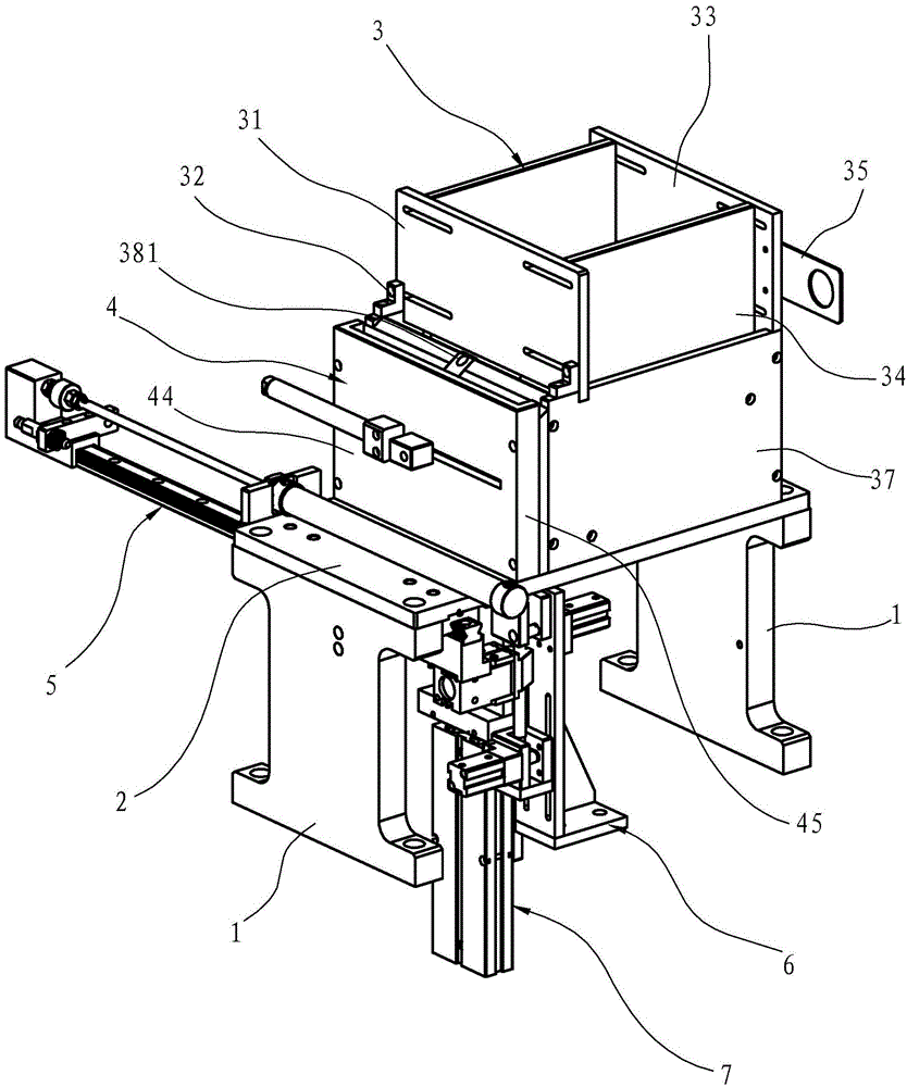
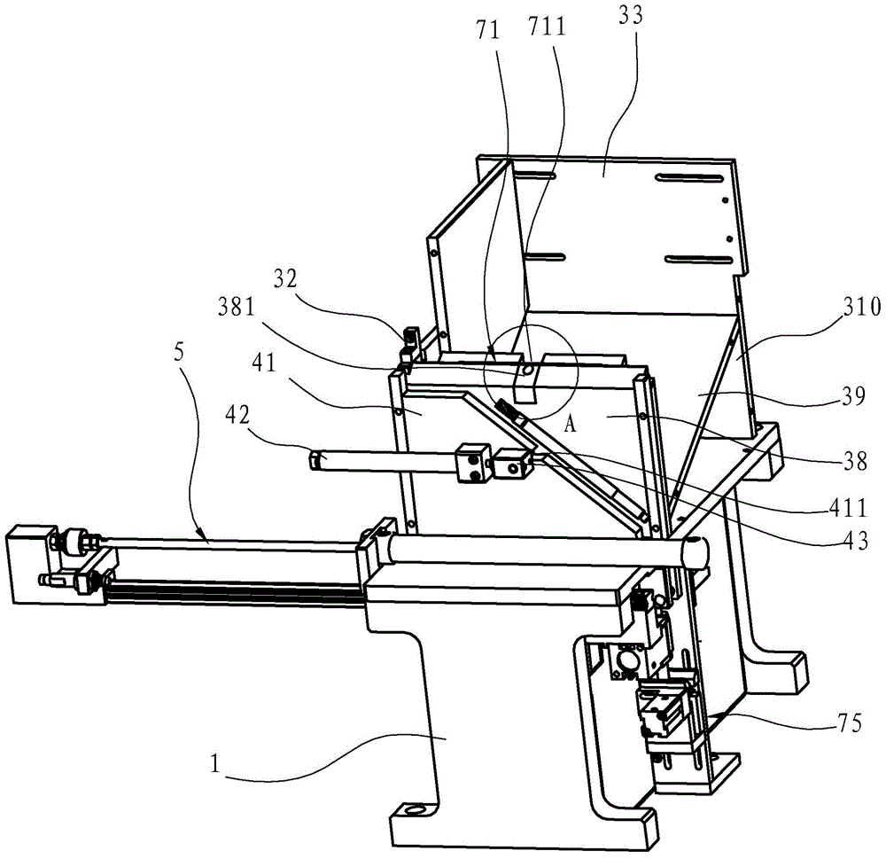
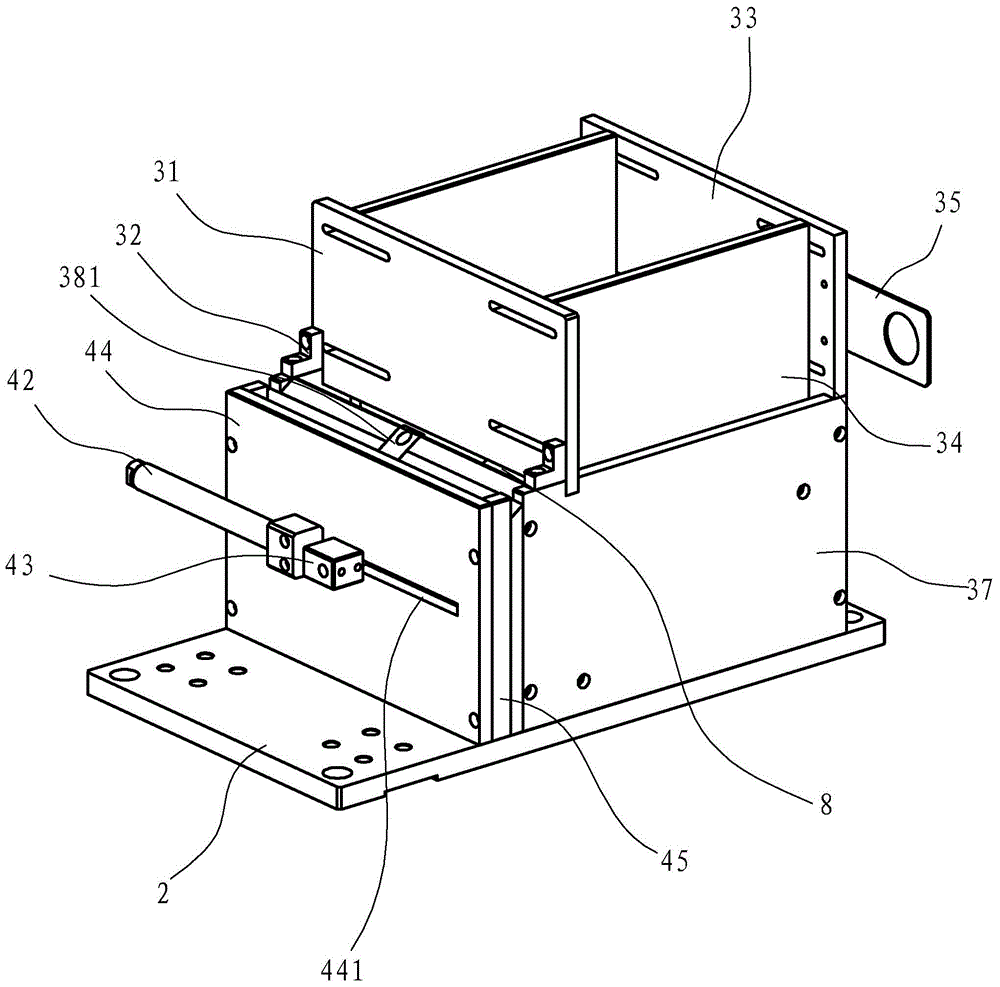
[0025] Such as Figures 1 to 7 As shown, the present invention discloses an automatic feeding mechanism for quenching shaft workpieces, including two vertical plates 1 oppositely arranged in an upright state, a flat plate 2 erected on the vertical plates 1, and a flat plate 2 arranged on the flat plate 2 so that The discharge box 3 placed horizontally for the shaft workpiece, the whole material box 4 arranged adjacent to the discharge box 3, and the feeding assembly for moving the shaft workpiece to the bottom of the air claw, the feeding assembly adopts the feeding slide rail assembly 5, of course A relatively simple structure may also be adopted.

[0026] Wherein, discharge box 3 upper openings comprise left and right side panels 37, front panel 38 and rear panel 310, the upper end face of this front panel 38 is the inclined surface incline...


PUM


Abstract

An automatic feeding mechanism used for quenching of shaft type workpieces is disclosed. The automatic feeding mechanism is characterized in that the automatic feeding mechanism comprises a material layout box allowing shaft type workpieces to be disposed transversely, a material arrangement box adjacent to the material layout box, and a conveying assembly for conveying the shaft type workpieces to a quenching station; the top of the material arrangement box is open; a material jacking plate passing through the bottom plate of the material layout box and jacking the shaft type workpieces in the material layout box up into the material arrangement box is disposed longitudinally in the material layout box; a material receiving inclined plate one side of which is inclined is disposed in the material arrangement box so that the shaft type workpieces jacked up into the material arrangement box are in an inclined state; an erecting pushing element for converting the shaft type workpieces in the inclined state into longitudinally erect shaft type workpieces is disposed at the material arrangement box; the bottom of the material arrangement box is provided with an opening through which the longitudinally erect shaft type workpieces can pass; the conveying assembly comprises a conveying pushing element, a clamping jaw pushed by the conveying pushing element and used for clamping the longitudinally erect shaft type workpieces; and trace bending deflection caused by traditional transverse quenching is avoided, thus improving quenching quality and increasing the quenching efficiency of the shaft type workpieces.

Description

technical field [0001] The invention relates to an automatic feeding mechanism for quenching shaft workpieces (especially motor mandrels). Background technique [0002] Quenching refers to a heat treatment method that uses high-frequency current (30K-1000KHZ) to locally heat and cool the surface of the workpiece to obtain a surface hardened layer. This method only strengthens the surface of the workpiece at a certain depth, while the core basically maintains the structure and performance before treatment, so it can obtain a combination of high strength, high wear resistance and high toughness. And because of local heating, it can significantly reduce quenching deformation and reduce energy consumption. [0003] The traditional manual quenching method is that the worker directly holds the workpiece, puts the part of the workpiece that needs to be quenched into the induction coil with high-frequency current, and waits for the workpiece to be heated to a certain level, and the...

Claims


Application Information

Patent Timeline
Patent Type & Authority Applications(China)
IPC IPC(8): C21D1/62C21D9/28
Inventor 陈剑伦
Owner NINGBO HAWK ELECTRICAL APPLIANCE CO LTD
Why Eureka
Try Eureka