Blade root and wheel groove structure of turbine moving blade

A technology of wheel grooves and blades, which is applied in the direction of supporting components of blades, machines/engines, mechanical equipment, etc., and can solve problems such as not being able to meet the design of longer blades

Inactive Publication Date: 2015-08-12
DONGFANG TURBINE CO LTD
View PDF7 Cites 4 Cited by
  • Summary
  • Abstract
  • Description
  • Claims
  • Application Information

AI Technical Summary

Problems solved by technology

The original fir tree-shaped blade root and wheel groove profile design can no longer meet the strength requirements of longer blade design and centrifugal force of 1000 tons or more

Method used


Image

  • Blade root and wheel groove structure of turbine moving blade
  • Blade root and wheel groove structure of turbine moving blade
  • Blade root and wheel groove structure of turbine moving blade

Examples


Embodiment Construction

[0018] Taking the 55-inch final stage blade of a full-speed thermal power steam turbine with a back pressure of 4KPa~13KPa, a power of 4F-1200MW~1400MW or 2F-600MW~700MW or 1F-300MW~350MW, and a speed of 3000r / min as an example, this will be explained in detail. invention.

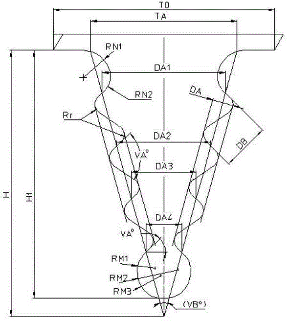
[0019] Such as figure 1 shown.

[0020] The blade root and the wheel groove structure of the turbine motor blade of the present invention, the blade root of the blade is assembled in the wheel groove of the impeller, the profile line of the blade root and the wheel groove is a fir tree type, and the fir tree type blade The root has four teeth and has characteristic parameters: the transition fillet radius Rr of the working tooth; the root pitch T0 of the blade root platform; the pitch TA at the top of the blade root; the theoretical height H of the blade root; the effective height H1 of the blade root; the height DA of the working tooth ; The distance DB between two adjacent pairs of tooth working faces,...


PUM


Abstract

A blade root and wheel groove structure of a turbine moving blade is disclosed. A blade root of the blade is assembled in a wheel groove of an impeller, and the contours of the blade root and the wheel groove are fir-shaped. The fir-shaped blade root has four teeth, and the contour of the transition position between the first tooth of the blade root and a blade root platform is formed by smoothly connecting through a linear section and two arc sections in different radius, wherein the connection points are tangential points. A linear line is a portion of bottom projection line of the blade root platform and is arranged in the upper side. The arc section with a large radius is arranged in the middle, and the arc section with a small radius is arranged in the lower side, wherein the large radius RN1 is 1.75 times of the small radius RN2. The fillet contour of a fourth tooth is formed by connecting of three arc sections with different radiuses in tangential manner. From top to bottom, the radius RM1 of a first arc section is 1.13 times of the RN2, the radius RM2 of a second arc section is 2.63 times of the RN2, and the radius RM3 of a third arc section is 1.44 times of the RN2. The blade root bearing capacity reaches over 1000 tons. The blade root and wheel groove structure is suitable for final-stage moving blades of super-large power turbines.

Description

Technical field: [0001] The invention relates to a turbine blade, and more particularly to the blade root and groove structure of the blade. Background technique: [0002] In recent years, with the rapid growth of my country's GDP, the consumption of energy has intensified. In 2012, my country's installed power capacity reached 1.14 billion kilowatts, most of which were thermal power generation. Since the consumption of a large amount of coal has aggravated the pollution of the environment, it is required that we must improve the efficiency of power generation and the utilization efficiency of energy. The technology of steam turbines for power generation is also developing in the direction of high parameters, large capacity, high efficiency, high reliability and environmental protection. From the perspective of the development of the unit with the largest single-unit capacity, the increase of the single-unit capacity is to increase the number of steam exhaust outlets of the...

Claims


Application Information

Patent Timeline
Patent Type & Authority Applications(China)
IPC IPC(8): F01D5/30
Inventor 周显丁范小平钟刚云范志飞王顺德尹明艳陈铁宁苟小平蒲守武倪长辉
Owner DONGFANG TURBINE CO LTD
Why Eureka
Try Eureka