Oil feeding device

A technology of oil replenishment device and oil injection hole, which is applied in the directions of fluid pressure actuating device, fluid pressure actuating system components, mechanical equipment, etc., can solve problems such as low oil replenishment efficiency

Inactive Publication Date: 2015-08-12
ZHUZHOU ELECTRIC LOCOMOTIVE CO
View PDF6 Cites 2 Cited by
  • Summary
  • Abstract
  • Description
  • Claims
  • Application Information

AI Technical Summary

Problems solved by technology

[0006] The purpose of the present invention is to provide an oil replenish

Method used


Image

  • Oil feeding device
  • Oil feeding device

Examples


Embodiment Construction

[0019] The core of the present invention is to provide an oil replenishing device, which can improve the working efficiency of oil replenishment.

[0020] In order to enable those skilled in the art to better understand the solution of the present invention, the present invention will be further described in detail below in conjunction with the accompanying drawings and specific embodiments.

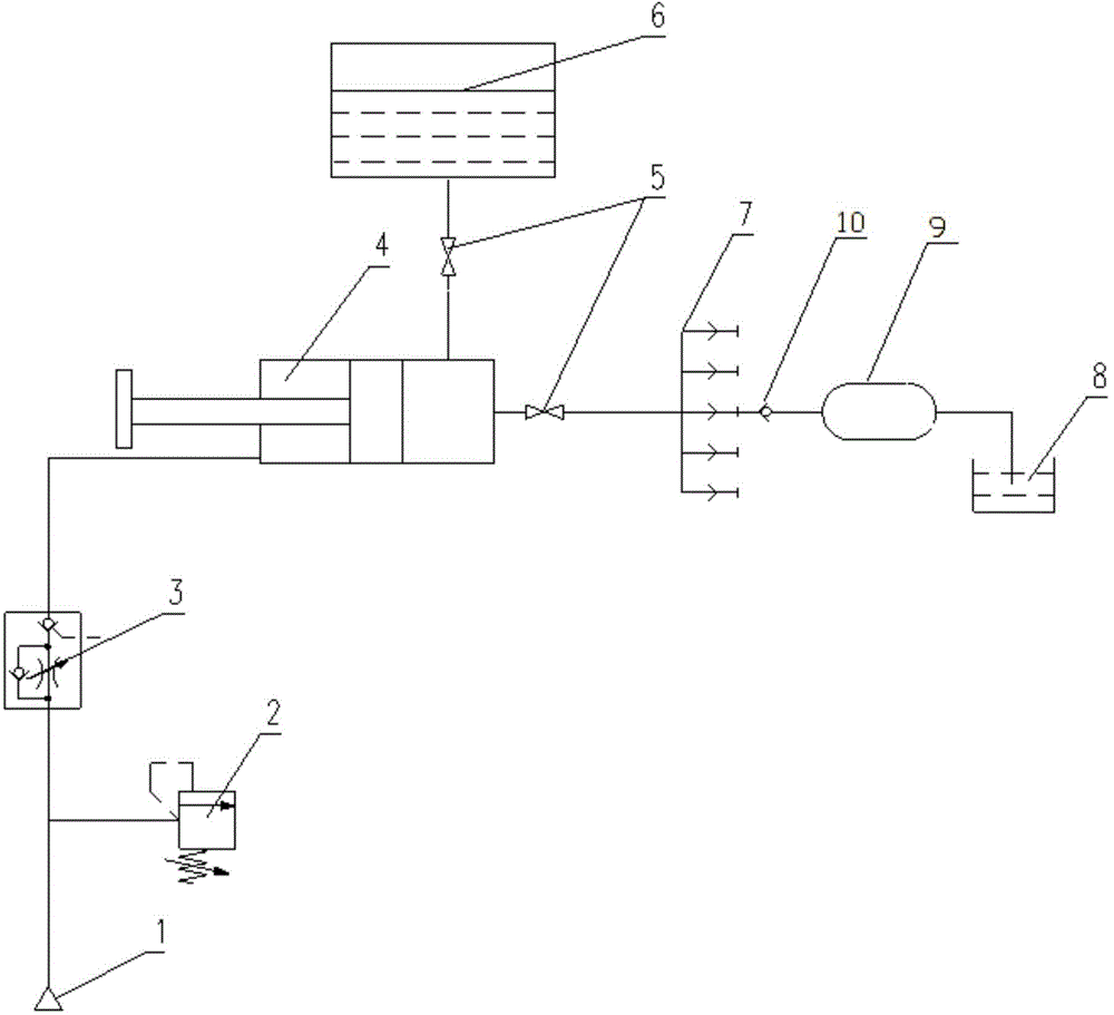
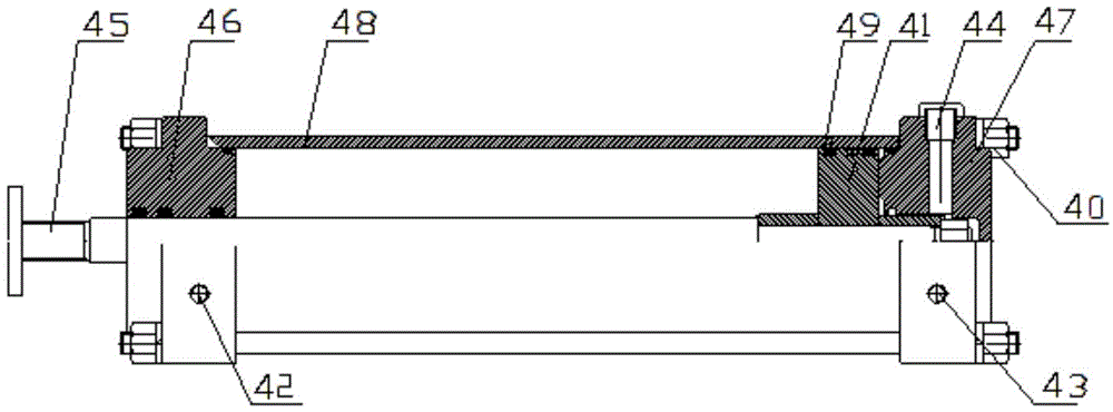
[0021] Please refer to figure 1 and figure 2 , figure 1 Schematic diagram of the structure of the oil supply device provided by the embodiment of the present invention; figure 2 for figure 1 Schematic diagram of the hydraulic cylinder in .

[0022] The oil supply device provided by the present invention comprises a hydraulic cylinder 4; the hydraulic cylinder 4 comprises a cylinder piston 41, a gas chamber and a liquid chamber, and the cylinder piston 41 separates the gas chamber and the liquid chamber; The air inlet 42 for kinetic energy, the liquid chamber is provided with the o...


PUM


Abstract

The invention discloses an oil feeding device comprising a hydraulic cylinder. A cylinder body piston separates a gas chamber from a liquid chamber. The gas chamber is provided with a gas inlet which provides kinetic energy for the cylinder body piston. The liquid chamber is provided with an oil outlet through which oil is fed into a vehicle hydraulic system. An integrated quick connector is arranged between the oil outlet and the hydraulic system. The liquid chamber is further provided with an oil injection hole used to feed oil into the vehicle hydraulic system, and the oil injection hole is connected with an oil storage tank. A cut-off valve is arranged between the oil injection hole and the oil storage tank, and a cut-off valve is arranged between the oil outlet and the integrated quick connector. The oil feeding device further comprises an oil return tank which is connected with the hydraulic system to realize oil return and gas discharge. A safety valve used for pressure relief is arranged between the gas inlet and a gas source. A pilot-operated one-way speed control valve used for controlling the oil feeding speed is arranged between the safety valve and the gas inlet. By adopting the oil feeding device, air can be prevented from entering the hydraulic system to affect the execution thereof, and the purpose of efficient and safe oil feeding is achieved.

Description

technical field [0001] The invention relates to the technical field of mechanical engineering, in particular to an oil replenishing device. Background technique [0002] With the rapid development of my country's track construction, the market demand for various types of oil replenishment devices is increasing. [0003] At present, the brake actuators and rescue support components of most maglev vehicles adopt the method of gas-hydraulic pressurization. Due to the complicated connection of hydraulic pipelines, there are many leakage points; therefore, any leakage of pipelines or internal pressure of hydraulic components Leakage will directly affect the execution force of hydraulic actuators and threaten driving safety. [0004] In the prior art, manual oil replenishment is usually used; since the circuits of the hydraulic components of the magnetic levitation vehicle are relatively independent, when leakage occurs in multiple circuits, oil must be manually replenished one b...

Claims


Application Information

Patent Timeline
IPC IPC(8): F15B21/00
CPCF15B21/005
Inventor 王明华佟来生罗华军毛莉高峰宋丽伟
Owner ZHUZHOU ELECTRIC LOCOMOTIVE CO
Why Eureka
Try Eureka