Heating devices used for bearing protection of aerogenerator and bearing system

A technology for wind turbines and heating devices, which is applied to wind turbine components, wind engines, and wind power generation. It can solve problems such as fracture of bearing parts, loss of interference, and surface peeling, so as to achieve close contact and prolong service life. , maintain the effect of fluidization

Active Publication Date: 2015-08-12
BEIJING GOLDWIND SCI & CREATION WINDPOWER EQUIP
View PDF5 Cites 15 Cited by
  • Summary
  • Abstract
  • Description
  • Claims
  • Application Information

AI Technical Summary

Problems solved by technology

According to incomplete statistics, 30% of the failures of shaft transmission parts are due to the relative rotation between the shaft and the inner ring of the bearing, resulting in joint failure.
In the case of relative rotation between the shaft and the bearing ring, the journal and the inner ring of the bearing are in a state of friction, and finally the size of the journal is smaller than the size of the inner ring, resulting in "lost" interference, the mounting surface of the journal is scrapped, and the inner ring is scrapped
[0013] In the case that the rolling bearing grease has frozen or lost its "fluidization", the resistance increases a lot due to the grease state between the rolling elements and the cage, and the friction between the rolling elements and the inner ring cannot support the resistance at start-up. It is easy to cause the rolling element and its cage to slip as a whole
After the grease freezes or loses its "fluidization", the main reasons for the slippage of the rolling elements in the load-bearing area are: ①The friction coefficient becomes smaller as the rolling elements freeze just after entering the load-bearing area; ②The grease freezes and causes the rolling elements to rely on the cage to form an integrated , leading to a lot of resistance increase; ③Sudden wind or gust of wind during low temperature period, the unit starts quickly and the bearing speed changes too fast, resulting in slippage
[0014] 5. Hazards caused by grease freezing and slipping
[0017] ②The "sliding friction" between the contact parts of the rolling bearing will generate huge heat, which will cause the temperature of the rolling bearing and lubricating oil to rise, thereby causing thermal deformation of the rolling bearing. Excessive thermal stress during work will cause the bearing parts to break or plastically deform. The indentation is formed on the surface of the bearing, which makes the bearing produce severe vibration noise during operation, causing peeling off of the nearby surface
Multiple sustained actions can lead to bearing failure

Method used


Image

  • Heating devices used for bearing protection of aerogenerator and bearing system
  • Heating devices used for bearing protection of aerogenerator and bearing system
  • Heating devices used for bearing protection of aerogenerator and bearing system

Examples


Embodiment 1

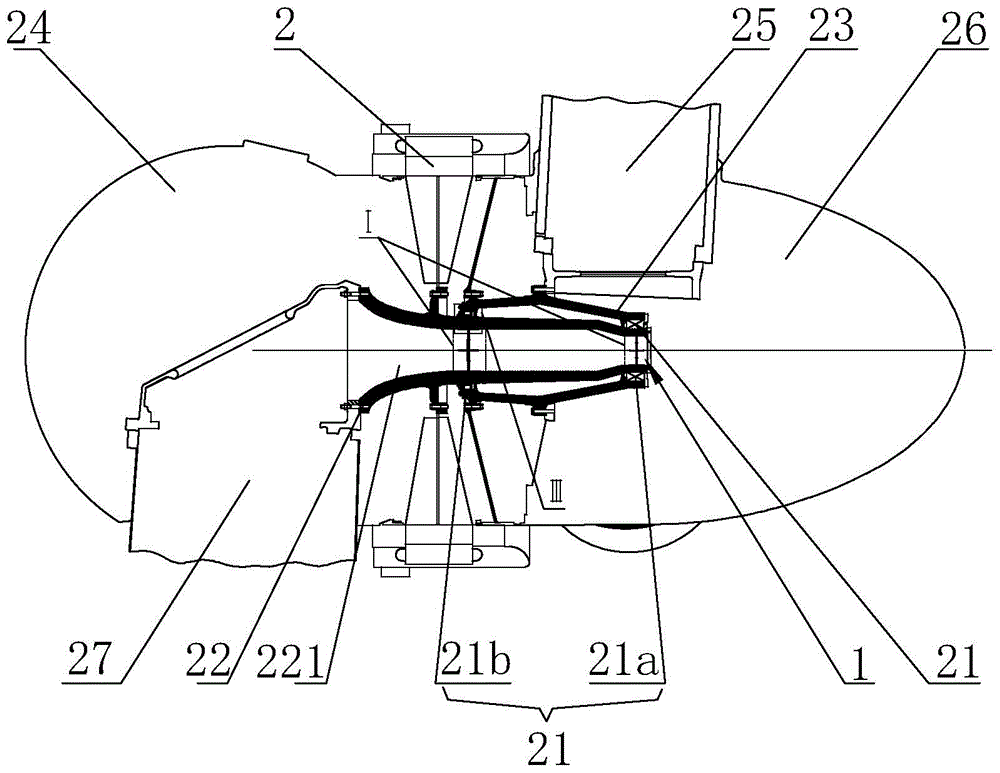
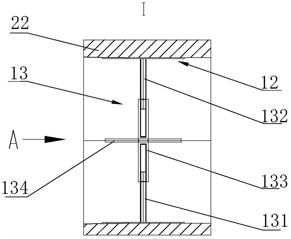
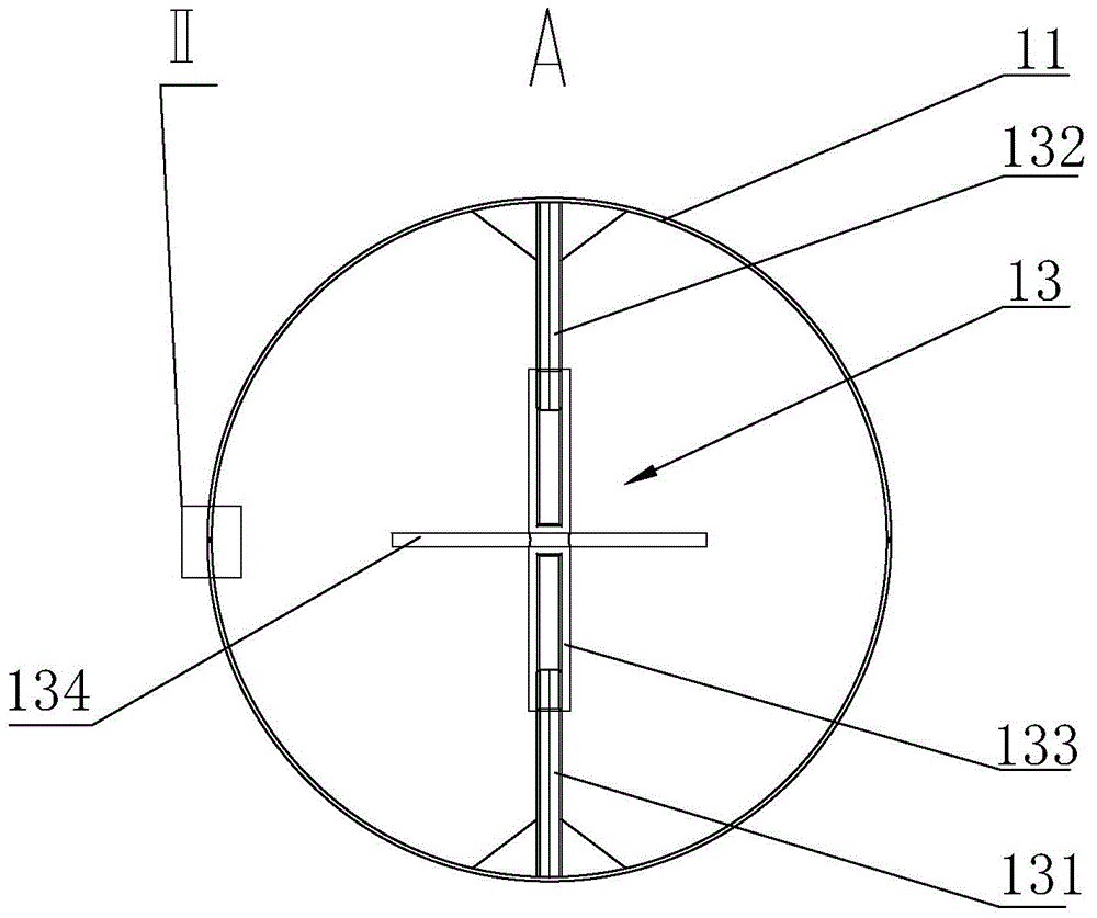
[0058] Such as Figure 1 to Figure 3 as shown, figure 1 It is a schematic diagram of the installation structure of the heating device in the embodiment of the present invention in the wind power generator, figure 2 for figure 1 Partial enlarged view of I in the structure shown, image 3 for figure 2 Front view of the structure shown at A.

[0059] The embodiment of the present invention provides a heating device 1 for bearing protection of a wind-driven generator, which can be applied to the main shaft of a wind-driven generator with bearings sleeved on the outside. The heating device 1 is placed inside the main shaft and passes through the inner wall of the main shaft. Heat the bearings that fit on the outside. In a wind turbine, both the stator and the rotor have their own main shafts. The main shaft of the stator is called the fixed shaft for short, and the main shaft of the rotor is called the moving shaft for short. According to the structure of the wind power gene...

Embodiment 2

[0073] refer to figure 1 , this embodiment relates to a bearing system of a wind power generator, mainly including the main shaft of the wind power generator and the paddle side bearing 21a and the tower side bearing 21b sleeved on the main shaft, inside the main shaft and with the paddle side bearing 21a and / or Or the heating device 1 described in the first embodiment above is provided at the position corresponding to the tower side bearing 21b.

[0074] Further, the above-mentioned wind power generator can have a structure of an outer rotor and an inner stator, then the main shaft is the fixed shaft of the wind power generator, and the moving shaft of the wind power generator is set on the fixed shaft through the tower side bearing and the paddle side bearing. outside of the shaft.

[0075] As another modification, the wind generator can also adopt the structure of the outer stator and the inner rotor, then the above-mentioned main shaft is the moving shaft of the wind gene...


PUM


Abstract

The invention provides heating devices used for bearing protection of an aerogenerator and a bearing system. The heating devices are applied to main shafts externally sleeve joint with bearings. The heating devices are arranged in interiors of the main shafts and correspond to positions where the bearings are disposed in terms of positions. Each heating device comprises multiple circular arc segments, a flexible heat source and a support device. Each flexile heat source is arranged between each circular arc segment and the inner wall of each main shaft. Each support device is used for the inner surface of each circular arc segment such that each flexible heat source is closely attached to the inner wall of each main shaft. The heating devices used for bearing protection of the aerogenerator and the bearing system have following beneficial effects: due to the fact that flexible heat sources are enabled to be closely fixed on inner walls of main shafts of the aerogenerator by means of combination among support devices and multiple circular arc segments, heat sources are provided for the bearings such that bearing grease is not frozen and fluidzed state of lubricating grease can be maintained; and service lifetime of bearings is prolonged in order to achieve close contact among the flexible heat sources and the inner walls of the main shafts of the aerogenerator.

Description

technical field [0001] The invention relates to a heating device for bearing protection of a wind power generator and a bearing system thereof, belonging to the technical field of wind power generation. Background technique [0002] In the shaft system of the permanent magnet direct drive outer rotor wind power generator, a bearing is usually arranged between the main shaft of the stator and the moving shaft of the rotor, and bearing grease is arranged at the bearing. [0003] 1. The role of bearing lubrication [0004] Due to the deviation of manufacturing accuracy and the deviation caused by the deformation of each part of the bearing during loading, rolling bearings cause direct contact and sliding friction between rolling elements and raceways, between rolling elements and cages, and between cages and inner and outer rings. The size of this sliding friction is related to the speed of the bearing and the load of the bearing. When the speed increases and the load increas...

Claims


Application Information

Patent Timeline
IPC IPC(8): F16N39/04F03D11/00
CPCF16N39/04F16C19/26F16C19/525F05B2240/54F05B2240/60F16C2360/31Y02E10/72F03D80/40F03D80/70F16C37/007
Inventor 马盛骏刘承前李永生
Owner BEIJING GOLDWIND SCI & CREATION WINDPOWER EQUIP
Why Eureka
Try Eureka