
Onsite detection device and method for pressure sensor of valve cooling system

A pressure sensor and system pressure technology, which is applied in the direction of measuring devices, measuring fluid pressure, instruments, etc., can solve the problems of substandard verification process, over-range damage of the meter head, and low reliability, so as to save detection time and improve reliability Effect

Active Publication Date: 2015-08-12
EXAMING & EXPERIMENTAL CENT OF ULTRAHIGH VOLTAGE POWER TRANSMISSION COMPANY CHINA SOUTHEN POWER GRID
View PDF6 Cites 8 Cited by
  • Summary
  • Abstract
  • Description
  • Claims
  • Application Information

AI Technical Summary

Problems solved by technology

It can be easily carried to the site for inspection, but the manual pressure pump cannot accurately control the air pressure, resulting in substandard verification process, and there is a risk of over-range damage to the meter head due to manual operation errors; data calculation and qualification judgment need to be carried out manually, which is inefficient , the reliability is not high
The pressure calibration bench can accurately test the pressure sensor, but it needs to take down the instrument to be tested during the power outage maintenance period and send it to the laboratory for testing, which takes a long time, and the cost of building the laboratory and the calibration bench is high
[0004] In view of the urgent time for power outage maintenance, high precision requirements for instruments and meters, and the verification process to be standardized, the development of this device can make up for the defects of the pressure calibrator and the pressure calibrator, and can realize the portability of the detection device to the site of the converter station , and can accurately detect the pressure sensor of the pure water cooling control system of the diverter valve in the case of urgent power outage maintenance time

Method used


Image

  • Onsite detection device and method for pressure sensor of valve cooling system
  • Onsite detection device and method for pressure sensor of valve cooling system
  • Onsite detection device and method for pressure sensor of valve cooling system

Examples


Embodiment Construction

[0034] The present invention will be further described below in combination with specific embodiments.

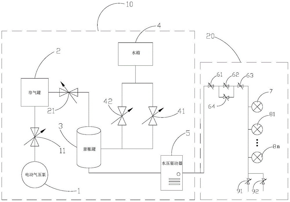
[0035] Please refer to figure 1 As shown, an on-site detection device for a pressure sensor of a valve cooling system includes a pressure controller 10 and a pressure calibration platform 20, wherein: the pressure controller 10 includes an electric pneumatic pump 1, an air storage tank 2, an expansion tank 3, and a water tank 4 , the output end of the electric pneumatic pump 1 is connected to the air inlet of the expansion tank 3 through the air storage tank 2, the water outlet of the water tank 4 is connected to the water inlet of the expansion tank 3, and the water outlet of the expansion tank 3 is connected to the The pressure calibration platform 20 is provided with a first manual valve 11 between the electric pneumatic pump 1 and the gas storage tank 2 , and a pressure switch 21 is provided between the gas storage tank 2 and the expansion tank 3 . Two passages are arr...


PUM


Abstract

The invention discloses an onsite detection device for a pressure sensor of a valve cooling system. The onsite detection device comprises a pressure controller and a pressure checking platform. The pressure controller comprises an electric pneumatic pump, an air storage tank, an expansion tank and a water box, wherein the output end of the electric pneumatic pump is connected to the air inlet of the expansion tank via the air storage tank, the water outlet of the water box is connected to the water inlet of the expansion tank, and the water outlet of the expansion tank is connected to the pressure checking platform. The pressure checking platform comprises a conveying pipeline, a control valve, the pressure sensor and a draining valve, wherein the water outlet of the expansion tank is connected to one end of the conveying pipeline, the draining valve is arranged at the other end of the conveying pipeline, the pressure sensor is mounted on the conveying pipeline, the control valve is mounted on the conveying pipeline between the pressure sensor and the expansion tank, and the pressure sensor comprises a pressure etalon and a meter to be detected. The invention also discloses an onsite detection method for the pressure sensor of the valve cooling system. Thus, full-automatic highly-reliable onsite pressure sensor detection with hydraulic pressure control is realized.

Description

technical field [0001] The invention relates to the technical field of high-voltage direct current transmission, in particular to an on-site detection device and method for a pressure sensor of a valve cooling system. Background technique [0002] The converter valve cooling system is a necessary auxiliary system for HVDC power transmission projects, and the converter valve cooling control system is an effective guarantee for reliable control and stable operation of the converter valve cooling system. The pipeline pressure of the valve cooling system of the direct current transmission project is used to provide power for the cooling water cycle, and the pressure sensor, as the signal acquisition unit of the converter valve cooling system, is an important part of it. By controlling the pressure between the valve towers, filter devices, water pump inlet and outlet in the cooling water cycle, the water cycle is guaranteed to be within the safe operation range of the system. ...

Claims


Application Information

Patent Timeline
Patent Type & Authority Applications(China)
IPC IPC(8): G01L27/00
Inventor 彭德辉钱海王海军卢志良陈欢张楠国建宝崔鹏飞王学之邬乾晋
Owner EXAMING & EXPERIMENTAL CENT OF ULTRAHIGH VOLTAGE POWER TRANSMISSION COMPANY CHINA SOUTHEN POWER GRID
Learn More