
Beam-formed ultrahigh frequency radio frequency identification reader-writer antenna linear array

A technology of radio frequency identification and beamforming, which is applied in the direction of antenna array, antenna, antenna support/installation device, etc., can solve the problems that the half-power beam width value cannot be accurately realized, the installation process is cumbersome, and the receiving dead angle is simple. , Realize the effect of beam scanning and low cost

Inactive Publication Date: 2015-08-12
WUYI UNIV
View PDF4 Cites 7 Cited by
  • Summary
  • Abstract
  • Description
  • Claims
  • Application Information

AI Technical Summary

Problems solved by technology

Radiation direction of traditional RFID reader antenna Figure 1 Generally, it has symmetry, but under certain conditions, it is only desired to identify the tags in a certain area, such as identifying the goods on the conveyor belt, the radiation energy of the reader antenna should be concentrated in the area near the conveyor belt; while in the area far above the conveyor belt , the radiation energy required is small, that is, the radiation pattern has a certain directivity; the antenna gain can be improved by forming an array, and the directivity of the antenna radiation pattern can be increased, but the antenna adopts equal-amplitude and same-phase feed, and the more More, the narrower the half-power beam width, the zero point between the main beam and the side lobe is likely to cause a dead angle of reception; in addition, the use of logarithmic periodic antennas and helical antennas added to the back cavity can make the radiated energy produce directivity, and installation needs Fixed at a certain angle, so that the maximum gain point of the pattern is aligned with the label reading area, the installation process is cumbersome, the cost is high, and the specified half-power beam width value cannot be accurately realized.

Method used


Image

  • Beam-formed ultrahigh frequency radio frequency identification reader-writer antenna linear array
  • Beam-formed ultrahigh frequency radio frequency identification reader-writer antenna linear array
  • Beam-formed ultrahigh frequency radio frequency identification reader-writer antenna linear array

Examples


Embodiment Construction

[0014] The content of the present invention will be further described below in conjunction with the accompanying drawings.

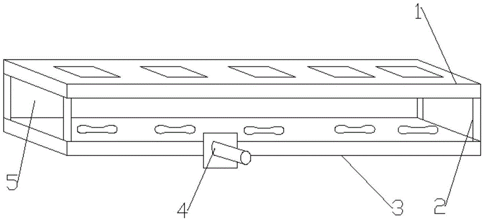
[0015] Such as figure 1 As shown, the beamforming UHF RFID reader antenna line array includes a radiation patch substrate 1, a feed network substrate 3 and a 50-ohm SMA connector 4; the radiation patch substrate 1 and the feed network substrate 3 are supported by The columns 2 are parallel and symmetrically connected, and an air layer 5 is formed between the radiation chip substrate 1 and the feed network substrate 3; the radiation unit of the radiation chip substrate 1 is a square copper sheet; the lower surface of the feed network substrate 3 is divided into five parts. Equal power divider, the input port is connected to 50 ohm SMA connector 4; the upper surface of the feed network substrate 3 is the ground surface and five dumbbell-shaped slots are etched, and the five dumbbell-shaped slots are respectively connected to the radiation unit of the uppe...


PUM


Abstract

The invention relates to a radio frequency identification reader-writer antenna linear array for emitting and receiving a radio signal, in particular a beam-formed ultrahigh frequency radio frequency identification reader-writer antenna linear array. A radiation patch substrate and a feed network substrate are in parallel symmetric connection through a support column, and an air layer is formed between the radiation patch substrate and the feed network substrate; radiation units of the radiation patch substrate are square copper sheets; the lower surface of the feed network substrate is a one-to-five unequal power distributor, an input port is connected with a 50Ohm SMA adaptor; the upper surface of the feed network substrate is a ground surface and five dumbbell shaped grooves are etched on the upper surface, the five dumbbell shaped grooves are respectively corresponding to radiation units on the above radiation patch substrate. The directivity of the wave beam is realized through the adoption of the beam-formed ultrahigh frequency radio frequency identification reader-writer antenna linear array provided by the invention; the antenna linear array has a downward inclination angle at 30 DEG and a half-power bandwidth at 25 DEG, and can be used for performing identification aiming at labels in a certain specific region, and the labels out of the region cannot be identified.

Description

technical field [0001] The invention relates to a radio frequency identification reader-writer antenna line array for transmitting and receiving radio signals, in particular to a beam-forming UHF radio frequency identification reader-writer antenna line array. Background technique [0002] For an RFID system, the reader antenna is an important part, it is used to transmit and receive signals, and is responsible for the important task of coupling energy to the tag. A good reader antenna can make the recognition effect reach the best state, and it is one of the key technologies for the good operation of the entire RFID system. The radiation direction of the traditional RFID reader antenna Figure 1 Generally, it has symmetry, but under certain conditions, it is only desired to identify the tags in a certain area, such as identifying the goods on the conveyor belt, the radiation energy of the reader antenna should be concentrated in the area near the conveyor belt; while in the...

Claims


Application Information

Patent Timeline
IPC IPC(8): H01Q1/38H01Q1/36H01Q23/00H01Q21/00H01Q1/22H01Q3/08
Inventor 张昕李子巍
Owner WUYI UNIV
Learn More