Electrostatic chuck and power supply system

A technology of electrostatic chuck and power supply system, which is applied in the direction of holding devices, clamping, and circuits using electrostatic attraction, which can solve the problems of high discharge suspicion, achieve the effects of simplifying the structure, avoiding damage, and reducing cables

Active Publication Date: 2015-08-12
CREATIVE TECH CORP
View PDF5 Cites 5 Cited by
  • Summary
  • Abstract
  • Description
  • Claims
  • Application Information

AI Technical Summary

Problems solved by technology

[0009] However, in the vacuum environment in the vacuum chamber 200, there is a high possibility of discharge between the voltage cables 220 and 220.

Method used


Image

  • Electrostatic chuck and power supply system
  • Electrostatic chuck and power supply system
  • Electrostatic chuck and power supply system

Examples


no. 1 example

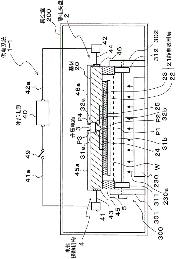
[0095] figure 1 It is a schematic cross-sectional view showing the electrostatic chuck and the power supply system according to the first embodiment of the present invention.

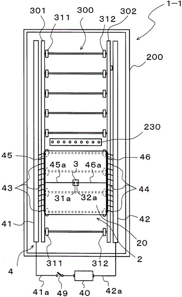
[0096] Such as figure 1 As shown, the power supply system 1-1 illustrated in this embodiment is a system for supplying external power to the electrostatic chuck 2 in the vacuum chamber 200 of the evaporation device, and is equipped with an electrostatic chuck 2 and an electric power supply. The contact mechanism 4, the electrostatic chuck 2 is transported by the transport mechanism 300.

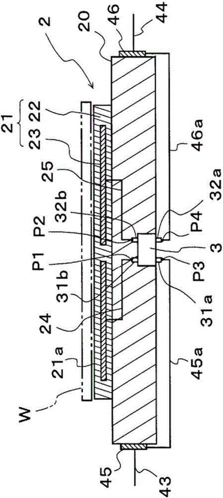
[0097] figure 2 is a cross-sectional view showing the electrostatic chuck 2 .

[0098] Such as figure 2 As shown, the electrostatic chuck 2 has a substrate 20 , an electrostatic adsorption layer 21 , and a booster circuit 3 .

[0099] The base material 20 is made of aluminum, SUS (Steel Use Stainless, stainless steel), iron, copper, titanium, ceramics (including ALN, SiC, Al 2 o 3 , SiN, zirconia (zirconia),...

no. 2 example

[0132] Hereinafter, the second embodiment of the present invention will be described.

[0133] Figure 4 In order to show the sectional view of the power supply system of the second embodiment of the present invention, and Figure 5 A schematic top view showing the power supply system.

[0134] In the power supply system 1 - 2 of this embodiment, the structure of the electrical contact mechanism is different from the electrical contact mechanism 4 of the power supply system 1 - 1 of the first embodiment described above.

[0135] exist Figure 4 Among them, symbol 6 is an electrical contact mechanism, and this electrical contact mechanism 6 is formed in a structure using rollers of the transport mechanism 300 .

[0136] Specifically, conductive rollers 61, 62 form multiple pairs of rollers 311, 312 in the transport mechanism 300 of the aforementioned first embodiment (refer to figure 1 ), and these rollers 61, 62 are used as fixed electrodes of the electrical contact mecha...

no. 3 example

[0143] Hereinafter, a third embodiment of the present invention will be described.

[0144] Figure 6 It is a schematic top view showing the power supply system of the third embodiment of the present invention.

[0145] The power supply system 1-3 of this embodiment is equipped with an electromagnetic induction device instead of the electrical contact mechanism of the foregoing embodiments, which is different from the power supply systems of the foregoing first and second embodiments.

[0146] exist Figure 6 Among them, symbol 7 is an electromagnetic induction device.

[0147] The electromagnetic induction device 7 is composed of a fixed coil 71 fixed in the vacuum chamber 200 and a movable coil 72 installed on the electrostatic chuck 2 .

[0148] The length of the fixed coil 71 is set to be substantially equal to the transfer range of the electrostatic chuck 2 , and both ends thereof are connected to the two terminals of the external power source 40 through cables 71 a an...


PUM


Abstract

[Problem] To provide an electrostatic chuck and a power supply system, wherein high-voltage drive is performed without generating electrical discharge even in a vacuum atmosphere, and a structure of the power supply system for the electrostatic chuck is simplified. [Solution] This power supply system is provided with: an electrostatic chuck (2) having a booster circuit (3); and an electric contact mechanism (4). Merely terminals (31a, 32a) of the booster circuit (3) are exposed to the outside. The terminals (31b, 32b) are connected to an attraction electrode (23). The electric contact mechanism (4) is configured from rails (41, 42), and flexible contacts (43, 44) in contact with the rails. The rails (41, 42) are connected to an external power supply (40), and the flexible contacts (43, 44) are provided on conductive plates (45, 46) of the electrostatic chuck (2). The conductive plates (45, 46) are connected to the terminals (31a, 32a) of the booster circuit (3).

Description

technical field [0001] The invention relates to an electrostatic chuck and a power supply system, which are used for absorbing processed plates such as glass substrates. Background technique [0002] Such as Figure 8 As shown, the electrostatic chuck 100 is generally fixed at the bottom of the vacuum chamber 200 of the processing device. In addition, a driving power supply voltage and an electrical signal are supplied to the electrostatic chuck 100 from a power supply 210 outside the vacuum chamber 200, so that the workpiece W is attracted to the electrostatic chuck 100 (for example, refer to Patent Document 1). [0003] However, in the above-mentioned system in which the electrostatic chuck 100 is fixed in the vacuum chamber 200, the processed plate W cannot be moved to a predetermined position in the vacuum chamber 200, or the processed plate W cannot be turned over. Less flexibility. [0004] Therefore, in recent years, a system in which the electrostatic chuck 100 is ...

Claims


Application Information

Patent Timeline
Patent Type & Authority Applications(China)
IPC IPC(8): H01L21/683B23Q3/15H02N13/00
CPCH01L21/6833H02N13/00
Inventor 辰巳良昭菅原利文
Owner CREATIVE TECH CORP
Why Eureka
Try Eureka