Polishing machine

A polishing machine and polishing brush technology, which is applied in the field of polishing machines, can solve problems such as scratches, customer dissatisfaction, and affecting the health of operators

Active Publication Date: 2015-08-19
山东精鹰机械制造有限公司
View PDF11 Cites 11 Cited by
  • Summary
  • Abstract
  • Description
  • Claims
  • Application Information

AI Technical Summary

Problems solved by technology

[0002] In the medical field, the steel plate for making tanks needs to be polished in advance. In order to make the surface of the steel plate reach a certain degree of smoothness, it is necessary to use multiple levels of polishing machines for multiple grinding and polishing. Therefore, the steel plate to be polished needs to be transported many times, and each time When polishing, it needs to be in contact with the discharge rack at the inlet and outlet end of the polishing machine. The more polishing stages, the more contact times between the steel plate and the feed rack, which greatly increases the possibility of scratches

Method used


Image

  • Polishing machine
  • Polishing machine
  • Polishing machine

Examples


Embodiment Construction

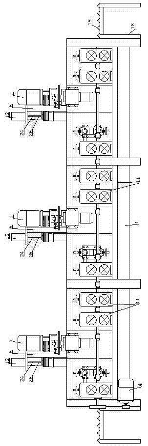
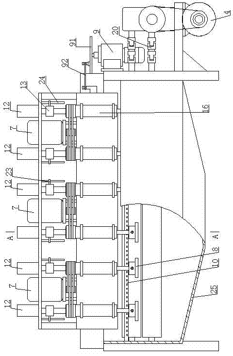
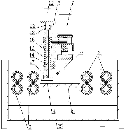
[0019] Such as Figure 1 to Figure 3 As shown, the polishing machine includes a frame 1, and the frame 1 is sequentially installed with three groups of mills from the feed end to the discharge end, and the frame 1 is respectively provided with a support frame 18 at the feed end and the discharge end, and the support frame The upper surface of 18 is fixed with universal support ball 19. Each group of mill feed end and discharge end are respectively equipped with two sets of conveying rollers to facilitate the smooth conveying of the steel plate. And the lower conveying roller 3 is a rubber roller, wherein the upper conveying roller 2 can be adjusted up and down, and the structure of up and down adjustment is a prior art, so it will not be repeated here. The main motor 4 used to drive the upper conveyor roller 2 and the lower conveyor roller 3 to rotate synchronously is installed on the frame 1. The conveyor roller groups at the feed end of each group of mills are respectively ...


PUM


Abstract

The invention discloses a polishing machine. The polishing machine comprises a machine frame, wherein multiple mills are installed on the machine frame, conveying roller sets are arranged at the feeding end and discharging end of the each mill, each conveying roller set comprises an upper conveying roller and a lower conveying roller, a main motor is installed on the machine frame, a working table used for supporting a steel plate to be machined is arranged between the feeding end and discharging end of each mill, and grinding head assemblies corresponding to the working tables are arranged on the machine frame. Each grinding head assembly comprises a sliding frame, a polishing motor and a polishing brush driven by the polishing motor to rotate, wherein the sliding frame is driven by a swing motor fixedly installed on the machine frame. The mesh numbers of the polishing brushes of the multiple mills become larger gradually from the feeding end to the discharging end of the machine frame. An injection pipe parallel to the corresponding conveying roller sets is installed on each mill, and multiple injection holes are formed in each injection pipe corresponding to the corresponding working table. Due to the fact that the mesh numbers of the polishing brushes of the multiple mills become larger gradually, polishing process requirements can be met at a time, and reciprocating scratching caused by repeated passing of the steel plates is avoided.

Description

technical field [0001] The invention relates to a polishing machine for polishing plate-shaped materials. Background technique [0002] In the field of medicine, the steel plate for making tanks needs to be polished in advance. In order to make the surface of the steel plate reach a certain degree of smoothness, it is necessary to use multiple levels of polishing machines for multiple grinding and polishing. Therefore, the steel plate to be polished needs to be transported many times, and each time When polishing, it needs to be in contact with the discharge rack at the inlet and outlet end of the polishing machine. The more polishing stages, the more contact times between the steel plate and the feed rack, which greatly increases the possibility of scratches on the surface of the steel plate, which may result in passing through the last stage. There are still large scratches on the surface of the ground and polished steel plate, which affects the quality of the steel plate,...

Claims


Application Information

Patent Timeline
IPC IPC(8): B24B29/06B24B57/02B24B41/00
CPCB24B29/06B24B41/005B24B57/02
Inventor 胡成刘圣德
Owner 山东精鹰机械制造有限公司
Why Eureka
Try Eureka