
Large-span steel box beam bridge deck pavement layer material gradient structure pavement construction method

A bridge deck paving and gradient structure technology, applied in bridges, bridge parts, bridge construction, etc., can solve the problems of adverse social impact, poor high temperature resistance of asphalt concrete, complicated construction, etc., and achieve excellent anti-rutting and anti-skid performance. , Improve the effect of low interface bond strength and improve driving comfort

Inactive Publication Date: 2015-08-19
NANTONG UNIVERSITY
View PDF4 Cites 21 Cited by
  • Summary
  • Abstract
  • Description
  • Claims
  • Application Information

AI Technical Summary

Problems solved by technology

At present, asphalt concrete is generally used for steel box girder bridge deck pavement. Steel is a good conductor of heat. In summer, the surface temperature of the steel plate is usually as high as 70°C or higher, while asphalt concrete has poor high temperature resistance. In the coupling effect of traffic load and high temperature Under the current situation, the asphalt concrete pavement layer will have defects such as shifting and overlapping when it is far from reaching the designed service life, and needs to be repaired every year, which will cause traffic jams and adverse social impacts, and bring huge economic losses to the country.
In addition, two types of pavement systems, epoxy asphalt and poured asphalt, are commonly used in domestic steel box girder bridge deck pavement. These two pavement systems have certain technical problems and the construction is extremely complicated, so they are not suitable for small working faces. , Application in urban steel box girder overpass pavement with complex construction environment

Method used


Image

  • Large-span steel box beam bridge deck pavement layer material gradient structure pavement construction method
  • Large-span steel box beam bridge deck pavement layer material gradient structure pavement construction method
  • Large-span steel box beam bridge deck pavement layer material gradient structure pavement construction method

Examples


Embodiment Construction

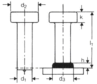
[0074] The present invention will be further described below in conjunction with the accompanying drawings and embodiments.

[0075] The present invention is suitable for pavement construction of gradient structure of bridge deck materials with a single-span span of steel box girder of various urban bridges within 150 meters (including 150 meters), and the design load is checked according to the vehicle-super 20 level and the trailer-120 level.

[0076] The process principle of the present invention is based on the principle of material gradient design, utilizes the maximum tensile stress of the pavement layer, the maximum shear stress between the pavement layer and the steel plate layer, and the elastic modulus ratio n (n=E pavement layer) of the bridge deck pavement system. / E steel plate) increases and gradually decreases, it is proposed to weld shear members on the steel plate (elastic modulus 210GPa), bind the steel mesh, and pour the lower layer of high-toughness lightwei...


PUM

PropertyMeasurementUnit
Heightaaaaaaaaaa

Abstract

The invention discloses a large-span steel box beam bridge deck pavement layer material gradient structure pavement construction method. The method comprises the steps that 1, derusting by sandblast and cleaning processing are conducted on an interface of a steel bridge deck; 2, shearing force parts are welded between a steel plate and a concrete pavement layer; 3, steel rib meshes are paved, and the steel rib meshes are bound to the shearing force parts; 4, high-strength toughening light concrete is poured; 5, a DPS waterproof layer is sprayed; 6, a bond stress absorbing layer is paved; 7, high-viscosity high-elastic SMA-13 bituminous mixtures are paved. According to the large-span steel box beam bridge deck pavement layer material gradient structure pavement construction method, polymers and fibers are added, the light aggregate concrete mix proportion design is optimized, the strength, the toughness, the deformability and the anti-fatigue performance of the light aggregate concrete are strengthened, and an optimal design on the arrangement of the shearing force studs and the steel rib meshes and the reinforcement ratio is conducted.

Description

technical field [0001] The invention relates to a bridge construction method, in particular to a large-span steel box girder bridge deck pavement layer material gradient structure pavement construction method. Background technique [0002] Steel bridge is one of the common bridge types in my country, mainly including steel box girder, steel truss, steel arch bridge, etc. Among them, steel box girder bridge has the advantages of light weight, economy, convenient erection, and large spanning capacity. , Widely used in large-scale cross-river and sea bridge projects. With the development of the bridge towards the direction of long span, it will have a broader application prospect. [0003] The bridge deck pavement is an important part of the bridge traffic system, which directly bears the load and the erosion of environmentally harmful substances. The performance of the pavement material and the rationality of the structural design are directly related to the durability, safety...

Claims


Application Information

Patent Timeline
IPC IPC(8): E01D19/12E01D21/00
CPCE01D21/00E01D19/083E01D19/125
Inventor 曹慧沈强儒成军康峰沂
Owner NANTONG UNIVERSITY
Learn More