Engine intake and exhaust control system and method

A technology of a control system and a control method, applied in the directions of engine control, electrical control, engine components, etc., can solve the problems of large size and weight of the supercharger, poor acceleration performance of the engine, large volume of the supercharger cavity, etc. Transient response performance, the effect of realizing intake air pressure ratio and increasing intake air volume

Inactive Publication Date: 2015-08-19
CHINA FAW LIMITED WUXI FUEL INJECTIONEQUIP RES INST +1
View PDF5 Cites 9 Cited by
  • Summary
  • Abstract
  • Description
  • Claims
  • Application Information

AI Technical Summary

Problems solved by technology

Since the fuel is in a high-energy liquid form, the fuel injection volume is easy to increase rapidly through the original injection system, but it is difficult to meet the air volume required in the transient state, and the transient response is poor, which leads to certain limitations in the improvement of power performance
In addition, the size and weight of the supercharger of a large engine are also often larger, resulting in a larger cavity volume of the supercharger and a larger inertial mass of the rotor
In the process of vehicle acceleration, due to the action of inertial force, there is often a certain lag in the air movement and rotor movement of the turbocharger, resulting in poor engine acceleration performance and poor emission performance during variable operating conditions
[0007] Generally speaking, the current exhaust gas recirculation EGR system and turbocharging system on the engine cannot meet the requirements of power performance and emission performance in the full range of working conditions, and there are still many problems to be solved urgently

Method used


Image

  • Engine intake and exhaust control system and method
  • Engine intake and exhaust control system and method

Examples


Embodiment Construction

[0034] The present invention will be further described in detail below in conjunction with the accompanying drawings and specific preferred embodiments.

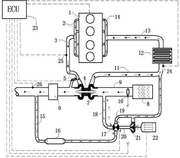
[0035] Such as figure 1 As shown, an engine intake and exhaust control system includes an engine 1 , an engine ECU 23 , an exhaust gas turbocharger, an air path control valve 17 and a double-effect pump 21 .

[0036] One end of the engine 1 is connected with an intake pipe 13 through an intake manifold 14 , an air cooler 12 is arranged on the intake pipe 13 , and the other end of the intake pipe 13 is connected with the intake manifold 11 . The other end of the engine 1 is connected with an exhaust manifold 3 through an exhaust manifold 2 . The intake manifold 11 is preferably provided with an intake manifold pressure sensor 24 for detecting the pressure of the fluid in the intake manifold 11 and transmitting the measured pressure to the engine ECU 23 in time. The exhaust manifold 3 is preferably provided with an exhaust m...


PUM


Abstract

The invention discloses an engine intake and exhaust control system and method. The engine intake and exhaust control system comprises an engine ECU, a gas circuit control valve and a double-effect pump. An exhaust gas bypass valve is arranged between an exhaust manifold and an exhaust pipe. The gas circuit control valve is connected with four gas circuits which are an EGR inlet pipe connected with the exhaust pipe, a bidirectional circulating pipe connected with an air inlet pipe, an intake branch pipe connected with an intake manifold and a pressurization gas pipe connected with the double-effect pump. The other end of the double-effect pump is connected with the intake branch pipe. On one hand, the double-effect pump serves as an EGR pump, enhances the capacity for introducing EGR exhaust gas and achieves stable adjustment of EGR within a whole working condition range; one the other hand, the double-effect pump serves as an electric air pressurizer, pressurizes air quickly and improves transient state response performance of an intake system. On-off conversion and control functions of the gas circuits are achieved through the gas circuit control valve, different requirements of an engine for recirculation exhaust gas or fresh air are met, and optimal power performance and exhaust performance are achieved.

Description

technical field [0001] The invention relates to an engine performance development control device and a control method, in particular to an engine intake and exhaust control method. Background technique [0002] With the increasingly stringent emission regulations, how to effectively improve the engine's power performance and reduce engine emissions while ensuring the engine's power performance and economic performance has become the focus of research and development. [0003] The working cycle of the engine is completed by multiple strokes. The intake and exhaust systems are the two important gas exchange boundaries of the open system of the engine. The oxygen in the system is completely controlled by the intake and exhaust systems, and the fuel that determines the power of the engine The amount of injection depends heavily on the amount of air entering the system, so the amount of air determines the power of the engine. [0004] The most common way to improve power perform...

Claims


Application Information

Patent Timeline
Patent Type & Authority Applications(China)
IPC IPC(8): F02M25/07F02B37/04F02B37/18F02B37/16F02D23/00F02D41/00
CPCY02T10/12
Inventor 郑金保缪雪龙赵智博夏少华居钰生
Owner CHINA FAW LIMITED WUXI FUEL INJECTIONEQUIP RES INST
Why Eureka
Try Eureka