Floating wave energy conversion device

An energy conversion device and floating technology, applied in ocean energy power generation, engine components, machines/engines, etc., can solve problems such as low efficiency conversion and inability to obtain energy output, so as to enhance overall stability and improve energy conversion and utilization Efficiency, low production cost effect

Active Publication Date: 2017-05-24
RES INST OF ECONOMICS & TECH STATE GRID SHANDONG ELECTRIC POWER +1
View PDF6 Cites 0 Cited by
  • Summary
  • Abstract
  • Description
  • Claims
  • Application Information

AI Technical Summary

Problems solved by technology

[0006] In view of the problems in the above-mentioned prior art that the traction rope is directly connected to the energy harvester, it is easy to cause the deflection of the energy harvester in one direction, so that the efficiency conversion is not high, and the stable energy output cannot be obtained. The purpose of the present invention is to provide a floating Wave energy conversion device, which can reduce the disordered shaking of the energy harvester, make the movement of the energy harvester approximately a regular reciprocating motion in the vertical direction, and drive the traction rope through the gear matched with the ring gear shaft, effectively improving the energy conversion efficiency, and obtain stable energy output

Method used


Image

  • Floating wave energy conversion device
  • Floating wave energy conversion device
  • Floating wave energy conversion device

Examples


Embodiment Construction

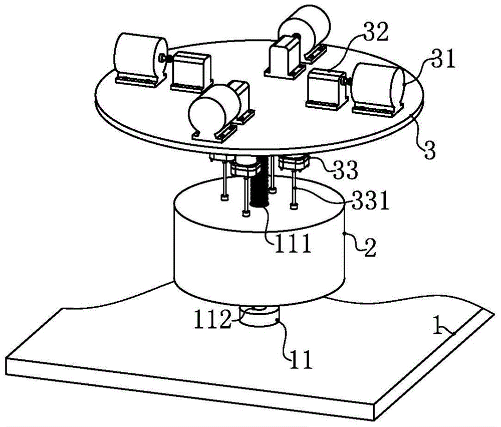
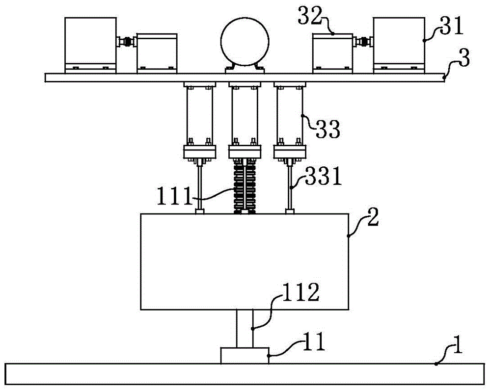
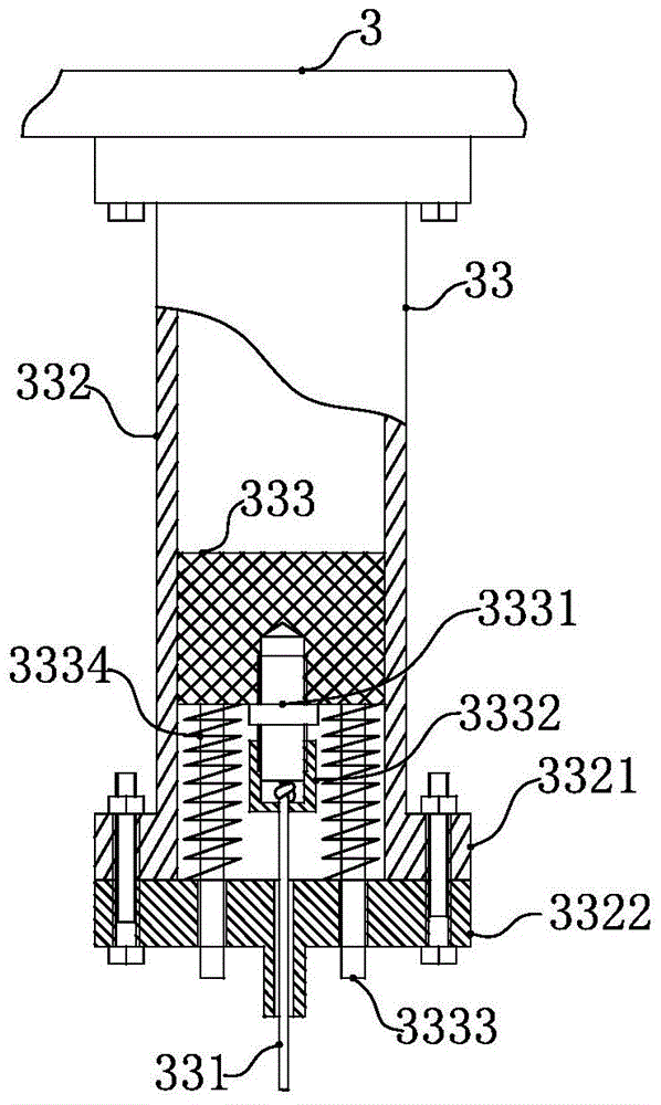
[0022] Such as Figure 1 to Figure 4 As shown, the present invention mainly includes a base 1, a generator 31, a hydraulic motor 32, an energy harvester 2 and a transducer 33. The traction rope 331 directly converts the mechanical energy of the energy harvester 2 into the pressure potential energy of the transducer 33; wherein, the generator 31 and the hydraulic motor 32 are all arranged on the upper side of the working platform 3, and the transducer 33 further The internal hydraulic medium drives the hydraulic motor 32 to rotate, and the hydraulic motor 32 drives the generator 31 to generate electricity.

[0023] The overall description of the general scheme of the present invention is described above, and the technical scheme and specific structure of the present invention will be described in detail below in conjunction with the accompanying drawings.

[0024] Such as figure 1 As shown, the base 1 is a seabed reef bed or an artificial installation platform, and the fixed ...


PUM


Abstract

The invention discloses a floating type sea wave energy conversion device which is used for mainly solving the problems that an energy collector is easy to have one-way deflection due to the fact that a hauling cable is directly connected with the energy collector, the efficiency conversion is low and stable energy output cannot be obtained. The floating type sea wave energy conversion device comprises a base, a generator, a hydraulic motor, the energy collector and an energy converter, wherein a fixing rod is arranged on the base; the fixing rod comprises an annular gear part and an optical shaft part; a gear matched with the annular gear part is arranged at the energy collector, a hauling cable winding wheel is arranged at one shaft end of the gear, and the energy collector is sleeved on the optical shaft part for moving up and down; the energy converter comprises a cylinder body, a piston, an end cover and the hauling cable; the hauling cable is connected between the piston and the hauling cable winding wheel, a guide column sleeved with a spiral spring is arranged between the end cover at the lower end of the energy collector and the piston, and the guide column penetrates through the end cover and is matched with the end cover with interval. The gear matched with the annular gear part is used for driving the piston for executing reciprocating motion through the hauling cable, the energy conversion efficiency is improved and stable energy output can be obtained.

Description

technical field [0001] The proposal relates to a disordered sea wave kinetic energy conversion device, specifically a floating sea wave energy conversion device. Background technique [0002] The ocean area accounts for 71% of the earth's area. Ocean wave energy occupies an important proportion in ocean energy. It is a rich, reliable and inexhaustible reliable energy source. The wave kinetic energy of seawater contains huge energy. It is estimated that the wave energy that is relatively easy to use in the world's oceans reaches more than 70 billion kilowatts, which has huge potential for development. [0003] my country has a coastline of 18,000 kilometers, and the offshore area is affected by the monsoon climate, especially under the action of the strong northerly wind in winter, forming a northeast-to-southwest large wave belt from the Yellow Sea to the South China Sea, with an average wave height of more than 2 meters. In 4-8 seconds, it has very considerable development ...

Claims


Application Information

Patent Timeline
Patent Type & Authority Patents(China)
IPC IPC(8): F03B13/22
CPCF03B13/22Y02E10/30
Inventor 张益于千千胡琳韩雪王奇张廷黄义波李小英宋洁
Owner RES INST OF ECONOMICS & TECH STATE GRID SHANDONG ELECTRIC POWER
Why Eureka
Try Eureka