ALD machining equipment and machining method
A technology of processing equipment and heaters, applied in metal material coating process, gaseous chemical plating, coating and other directions, can solve the problems of long cycle, difficult quality assurance, waste of precursor sources, etc.
- Summary
- Abstract
- Description
- Claims
- Application Information
AI Technical Summary
Problems solved by technology
Method used
Image
Examples
Embodiment 1
[0054]This example discloses an ALD processing apparatus.
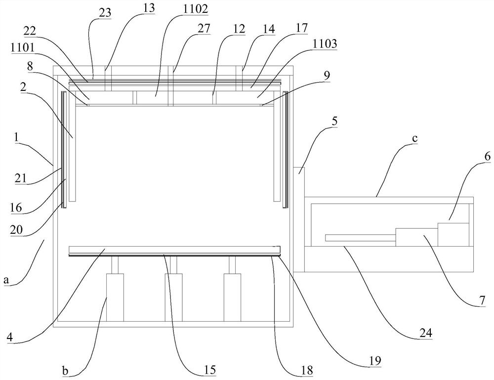
[0055]figure 1 Structure of an ALD processing apparatus disclosed in Example 1, combinedfigure 1 The ALD processing apparatus of the present embodiment includes reactor a, lifting device B, and a feed chamber C.
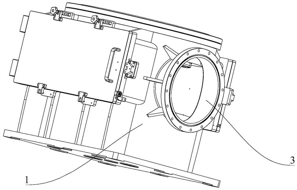
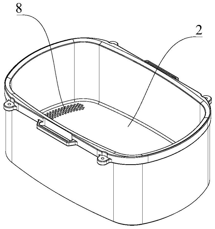
[0056]Combinefigure 1 The reactor A of the present embodiment includes a vacuum chamber 1 and a reaction chamber 2, and the reaction chamber 2 is built into the vacuum chamber 1,figure 2 A schematic structural diagram of the vacuum chamber of the present embodiment,image 3 Structure of the reaction chamber of the present embodiment, combinedFigure 1 - Figure 3The reactive chamber 2 of the present embodiment is open, and a delivery port is provided on the side of the vacuum chamber 1.
[0057]Combinefigure 1 The lifting device B of the present embodiment is disposed on the reactor A, and the output end of the lifting device B is vertically telescopically, and a cover 4 is provided on the output of the lifting device B, and ...
Embodiment 2
[0061]This embodiment provides a reaction chamber for use in an ALD processing apparatus shown in Example 1.
[0062]Figure 4 Structure of the reaction chamber of the present embodiment, combinedimage 3 as well asFigure 4 The bottom portion of the reaction chamber 2 of the present embodiment is provided with an intake passage 8 and an air passage 9, the intake passage 8, and the air passage 9 to be opposed to the center line of the top of the reaction chamber 2.
[0063]In this embodiment, the precursor source is injected into the reaction chamber 2 from the intake passage 8 of the reaction chamber 2, and is discharged from the air passage 9 of the reaction chamber 2, due to the intake passage 8 and the air passage 9 The centerline of the top of the reaction chamber 2 is disposed, so that the fluid field in the reaction chamber 2 is a laminar flow, and the intake and extravasation of the precursor source are in direct contact with the reaction chamber, avoiding the precursor source The ri...
Embodiment 3
[0069]This embodiment provides a reaction chamber, suitable for an ALD processing apparatus shown in Example 1 or 2.
[0070]Figure 5 The structural schematic view of the reaction chamber of Example 3, the reactive chamber shown in the present embodiment and the reaction chamber shown in Example 2 is that two uniform plate 10 is provided in the reaction chamber 2, The two homogeneous plates 10 are disposed opposite the center line of the top of the reaction chamber 2, and the two uniform plate 10 is disposed between the intake passage 8 and the air passage 9, and the two uniform plate 10 divide the reaction chamber into The intake chamber, the reaction chamber, and the vent chamber are provided with a plurality of through holes on each of the homogeneous plates 10.
[0071]The precursor source can enter into the intake chamber by the intake passage 8, and then passes into the reaction chamber by the homogenizing plate 10 on the same side of the intake chamber, and the substrate is purged,...
PUM
 Abstract
Description
Claims
Application Information
 - R&D
- Intellectual Property
- Life Sciences
- Materials
- Tech Scout
- Unparalleled Data Quality
- Higher Quality Content
- 60% Fewer Hallucinations
Browse by: Latest US Patents, China's latest patents, Technical Efficacy Thesaurus, Application Domain, Technology Topic, Popular Technical Reports.
© 2025 PatSnap. All rights reserved.Legal|Privacy policy|Modern Slavery Act Transparency Statement|Sitemap|About US| Contact US: help@patsnap.com


