

Supersonic ejector
A technology of supersonic speed and ejector, which is applied in the directions of jet pumps, fluid mixers, machines/engines, etc., and can solve the problems of the ejected airflow not having time to expand, interfere, and waste pressure energy, etc., and achieve simple installation, easy processing, The effect of air mixing is sufficient
- Summary
- Abstract
- Description
- Claims
- Application Information
AI Technical Summary
Problems solved by technology
Method used
Image

Examples
Embodiment Construction
[0021] The principles and features of the present invention will be described in detail below in conjunction with the accompanying drawings.
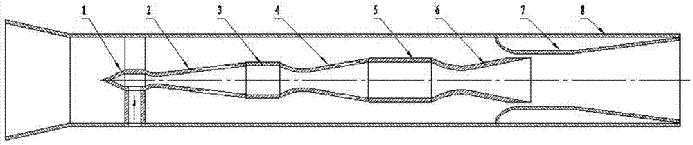
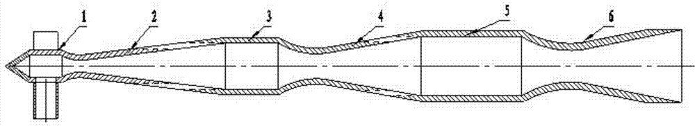
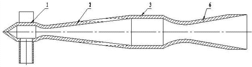
[0022] When the pressure of the gas source of the ejector is high, the nozzle is used to expand and compress the gas multiple times, and the serial staged air intake is adopted to improve the mixing efficiency and reduce the pressure loss. Reasonable distribution of intake air volume between stages is particularly important for improving ejection efficiency. figure 1 It is a structural diagram of a supersonic ejector, and the ejector includes: an intake pressure chamber 1, a nozzle 2, a mixing chamber 3, a nozzle 4, a mixing chamber 5, a tail nozzle 6, a supersonic diffuser section 7 and a shell cylinder 8. According to the design of the present invention, the above nozzles 2 and 4 are all Laval nozzles, and the peripheral walls of the expansion parts are provided with forward air inlet grooves. The nozzle 2, the mixing chamber 3, the...
PUM
 Abstract
Description
Claims
Application Information