
An identification method for electromagnetic excitation load of electric motor

A technology of electromagnetic excitation and identification method, which is applied in the testing of machines/structural components, vibration testing, measuring devices, etc., and can solve problems such as increasing the difficulty of testing and installation, inaccurate measurement, and potential safety hazards

Active Publication Date: 2017-07-18
中国船舶重工集团公司第七一二研究所
View PDF5 Cites 0 Cited by
  • Summary
  • Abstract
  • Description
  • Claims
  • Application Information

AI Technical Summary

Problems solved by technology

There are two main indirect measurement methods, one is to arrange the induction coil on the stator teeth of the motor, and measure the magnetic field characteristics through the change of the magnetic flux on the induction coil, but because it is arranged on the entire tooth, the measured value is the average value of the entire tooth, It is difficult to reflect the axial distribution of the magnetic field; the other is to install a very thin Hall effect sensor directly in the air gap between the motor stator and rotor, but because the Hall sensor has a certain thickness, this will affect the air gap between the stator and rotor However, the measurement is inaccurate, and in order to measure the axial and circumferential distribution, it is often necessary to arrange a large number of Hall sensors in a limited air gap, which will also increase the difficulty of test installation and cause certain safety hazards

Method used


Image

  • An identification method for electromagnetic excitation load of electric motor
  • An identification method for electromagnetic excitation load of electric motor
  • An identification method for electromagnetic excitation load of electric motor

Examples


Embodiment 1

[0024] Embodiment 1: is a basic embodiment. A method for identifying an electromagnetic excitation load of a motor, the steps of which are:

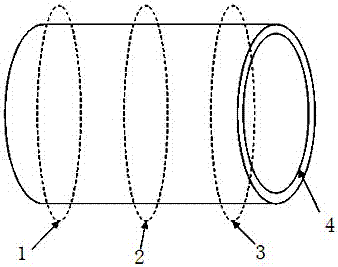
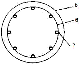
[0025] Step 1, determine the equivalent method of the electromagnetic excitation load: uniformly equivalent to the excitation force of three sections in the axial direction of the stator, and equivalent to eight excitation forces uniformly in the circumferential direction of each section, a total of 24 excitations force; the equivalent 24 excitation forces and the actual excitation force all have the effect of making the structure produce the same vibration response, and this equivalent excitation force can be used to simulate the loading of the excitation; the three sections are: the section near the non-driving end 1, the central section 2 and the section 3 near the driving end;

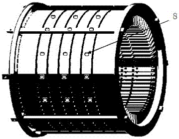
[0026] Step 2, measuring point arrangement: Determine the equivalent excitation point 7 of the electromagnetic excitation source of the motor, that is, arra...

Embodiment 2

[0030] Embodiment 2: it is a further embodiment: in the described step 3, it is based on the hammering method and utilizes the transfer function testing device to test the transfer function from the excitation point 7 to the reference point 8, and the transfer function testing device includes a force hammer 9, an acceleration Sensors, data acquisition front-end, and PC, the acceleration sensor is arranged at the reference point 8, and the force hammer 9 hits the excitation point 7 to generate a broadband pulse excitation force signal. The force hammer and the acceleration sensor are connected to the PC through the data acquisition front-end, and the data acquisition The data to be collected by the front end are: the excitation force signal generated by the hammer 9 hitting the excitation point 7, the vibration acceleration response signal of the reference point 8, and the data is processed by the PC into a transfer function from the excitation point 7 to the reference point 8. ...

Embodiment 3

[0033] Embodiment 3: be a preferred embodiment. Taking a large motor as an example, the present invention will be further described in conjunction with the accompanying drawings:

[0034] The main process includes: determining the equivalent excitation point 7 of the electromagnetic excitation source, the arrangement of the reference point 8, the transfer function test when the rotor is removed from the motor, the working condition response test of the reference point 8 under the rated operating condition of the motor, and the electromagnetic excitation Vibration load identification. details as follows:

[0035] 1. Determine the equivalent excitation point of the electromagnetic excitation source: for a large motor, the electromagnetic excitation source is mainly the radial electromagnetic force that the air gap magnetic field acts on the inner surface of the stator core. According to the radial electromagnetic force in time and space (stator axial and circumferential positi...


PUM


Abstract

The invention relates to an identification method of electromagnetic excitation load of a motor, which belongs to the field of structural acoustic design of electric motors, is suitable for identification of electromagnetic excitation load in structural acoustic design of electric motors and can be used for frequency characteristic analysis of electromagnetic excitation load of electric motors. The steps include: determining the equivalent method of the electromagnetic excitation load, measuring point arrangement, transfer function test, working condition response test and load identification. The invention has the advantages of improving the accuracy of identification of the electromagnetic excitation load of the motor, overcoming the difficulty of test installation in the traditional indirect test method, and considering the distribution characteristics of the electromagnetic excitation force with time and space, realizing the identification of the electromagnetic excitation load of the motor, etc. Efficiency calculation and frequency characteristic analysis, guiding the structural acoustic design of the motor, is a method for identifying the electromagnetic excitation load of the motor that is simple to test and install.

Description

technical field [0001] The invention relates to an identification method of an electromagnetic excitation load of a motor, which belongs to the field of structural acoustic design of a motor, and is suitable for the identification and frequency characteristic analysis of the electromagnetic excitation load in the structural acoustic design of a motor, and can be used for the simulation calculation of the structural vibration of a motor. Background technique [0002] For the motor, due to the interaction of the air-gap magnetic field, an electromagnetic excitation force that varies with time and space is generated on the stator and rotor. If the frequency of the electromagnetic excitation force is close to some modal frequencies of the motor structure, resonance will occur, causing The obvious increase of the motor vibration noise requires the study of the frequency characteristics of the electromagnetic excitation force. Since the electromagnetic exciting force on the motor ...

Claims


Application Information

Patent Timeline
IPC IPC(8): G01M7/02
Inventor 余虎张国兵田磊谭登洪
Owner 中国船舶重工集团公司第七一二研究所
Learn More