Clamp for battery charge-discharge test

A charge-discharge test and battery technology, applied in the direction of the casing of the measuring device, can solve the problems of unstable clamping of cylindrical batteries, easy short-circuit of batteries, etc., and achieve the effect of avoiding battery skew

Inactive Publication Date: 2015-08-19
BEIQI FOTON MOTOR CO LTD
View PDF5 Cites 7 Cited by
  • Summary
  • Abstract
  • Description
  • Claims
  • Application Information

AI Technical Summary

Problems solved by technology

[0005] This application solves the technical problem that the battery testing device in the prior art is unstable in clamping the cylindrical battery, which causes the battery to be easily short-circuited

Method used


Image

  • Clamp for battery charge-discharge test
  • Clamp for battery charge-discharge test
  • Clamp for battery charge-discharge test

Examples


Embodiment 1

[0047] This embodiment provides a battery charge and discharge test fixture, including:

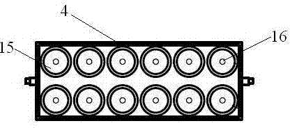
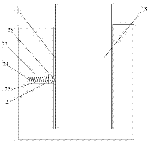
[0048] The base 3 is provided with a plurality of positioning grooves 4 on the base 3, each of the positioning grooves 4 is suitable for vertically inserting the battery 15, and the bottom end of each of the positioning grooves 4 is provided with a negative connection piece, so The negative connecting piece is connected to the charging and voltage sampling negative wire harness 7; the depth of the positioning groove 4 in this embodiment is 1 / 3 of the height of the battery 15; as an optional embodiment, the positioning groove 4 The depth can be set as 1 / 5-4 / 5 of the height of the battery 15; the reason is that within this depth range, the stable positioning of the battery can be realized, and at the same time, it is convenient to take and place the battery.

[0049] The upper cover, the upper cover in this embodiment is set as a flat plate, and a plurality of positive contacts are arranged...

Embodiment 2

[0053] The battery charge and discharge test fixture provided in this embodiment includes:

[0054] The base 3 is provided with a plurality of positioning slots 4 , each of which is suitable for vertically inserting a battery 15 , and a negative connection piece is provided at the bottom of each of the positioning slots 4 . The negative connecting piece is connected to the charging and voltage sampling negative wiring harness 7; the depth of the positioning groove 4 in this embodiment is 1 / 5 of the height of the battery 15.

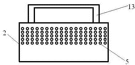
[0055] The upper cover, the upper cover includes a cover plate 1 and a cover body 2 connected to each other, and a plurality of positive contacts are arranged on the lower surface of the cover plate 1, and the positive contacts are connected with the charging and voltage sampling positive wire harness 6 connected, the plurality of positive contacts are set in one-to-one correspondence with the negative connecting pieces of the plurality of positioning gro...

Embodiment 3

[0058] The battery charge and discharge test fixture provided in this embodiment includes:

[0059] Base 3, such as figure 1 As shown, a plurality of positioning grooves 4 are provided on the base 3, each of the positioning grooves 4 is suitable for vertically inserting the battery 15, and the depth of the positioning grooves 4 in this embodiment is 100% of the height of the battery 15 3 / 5; a negative connection piece is provided at the bottom of each positioning slot 4, and the negative connection piece is connected to the charging and voltage sampling negative wire harness 7; between the upper surface and the lower surface of the base 3 An exhaust channel is provided, and the exhaust channel runs through a pair of sides of the base 3, and an exhaust fan 9 is arranged at both ends of the exhaust channel; each of the positioning grooves 4 is connected to the The exhaust channels are connected. Also be provided with temperature testing device in described locating groove 4; ...


PUM


Abstract

The invention provides a clamp for a battery charge-discharge test. The clamp is provided with a pedestal and an upper cover. A plurality of positioning grooves are arranged in the pedestal. Negative pole connecting sheets are arranged at the bottom ends of the positioning grooves. A plurality of positive pole contacts are arranged on the lower surface of the upper cover. When using, batteries are inserted into the positioning grooves vertically and the negative poles of the batteries press against the negative pole connecting sheets. Then the upper cover is arranged above the positioning grooves and the positive pole contacts press against the positive poles of the batteries inserted in the positioning grooves. In this way, performance parameters such as voltage characteristics and the like of the batteries can be tested. Since the batteries are inserted in the positioning grooves when the clamp provided by the invention is in use, battery inclination is avoided during the testing process, so that problems of battery inclination and pole short circuit due to insecure clamping of the batteries in the prior art are avoided.

Description

technical field [0001] The invention belongs to the field of battery testing devices, and in particular relates to a fixture for battery charging and discharging testing. Background technique [0002] In the prior art, wire welding or probe test fixtures are generally used for testing cylindrical batteries. Among them, the wire welding method is relatively simple to operate, just use the electric soldering iron and tin wire to weld the positive and negative electrodes of the battery and the wires together. But its disadvantage is that since the shell of the cylindrical battery is generally charged, and the soldering iron and tin wire used for welding are both conductors, a little carelessness when welding the positive lead will lead to the connection between the shell and the positive electrode. , so that the positive and negative poles of the battery are short-circuited, and there is a great potential safety hazard. [0003] Probe test fixture is a kind of battery test de...

Claims


Application Information

Patent Timeline
Patent Type & Authority Applications(China)
IPC IPC(8): G01R1/04
Inventor 马建生孙永贤赵景辉
Owner BEIQI FOTON MOTOR CO LTD
Why Eureka
Try Eureka