AI technical title is built by PatSnap AI team. It summarizes the technical point description of the patent document.
A radar antenna array and radar antenna technology, applied in the field of radar array antennas, can solve problems such as infeasibility, lack of effective algorithms, and expansion of solution space scale.
Active Publication Date: 2015-08-19
CENT SOUTH UNIV
View PDF4 Cites 27 Cited by
Summary
Abstract
Description
Claims
Application Information
AI Technical Summary
This helps you quickly interpret patents by identifying the three key elements:
Problems solved by technology
Method used
Benefits of technology
Problems solved by technology
However, as the number of array elements increases, the scale of the solution space of the problem expands exponentially. To find the optimal MR-MIMO array configuration in a short period of time, the exhaustive search method is no longer feasible.
At present, there is no effective algorithm to solve this problem in the literature
Method used
Image
Click on the blue label to locate the original text in one second.
Reading with bidirectional positioning of images and text.
Examples
Embodiment 1
[0088] Step 1. Initialization of array parameters and almost difference sets
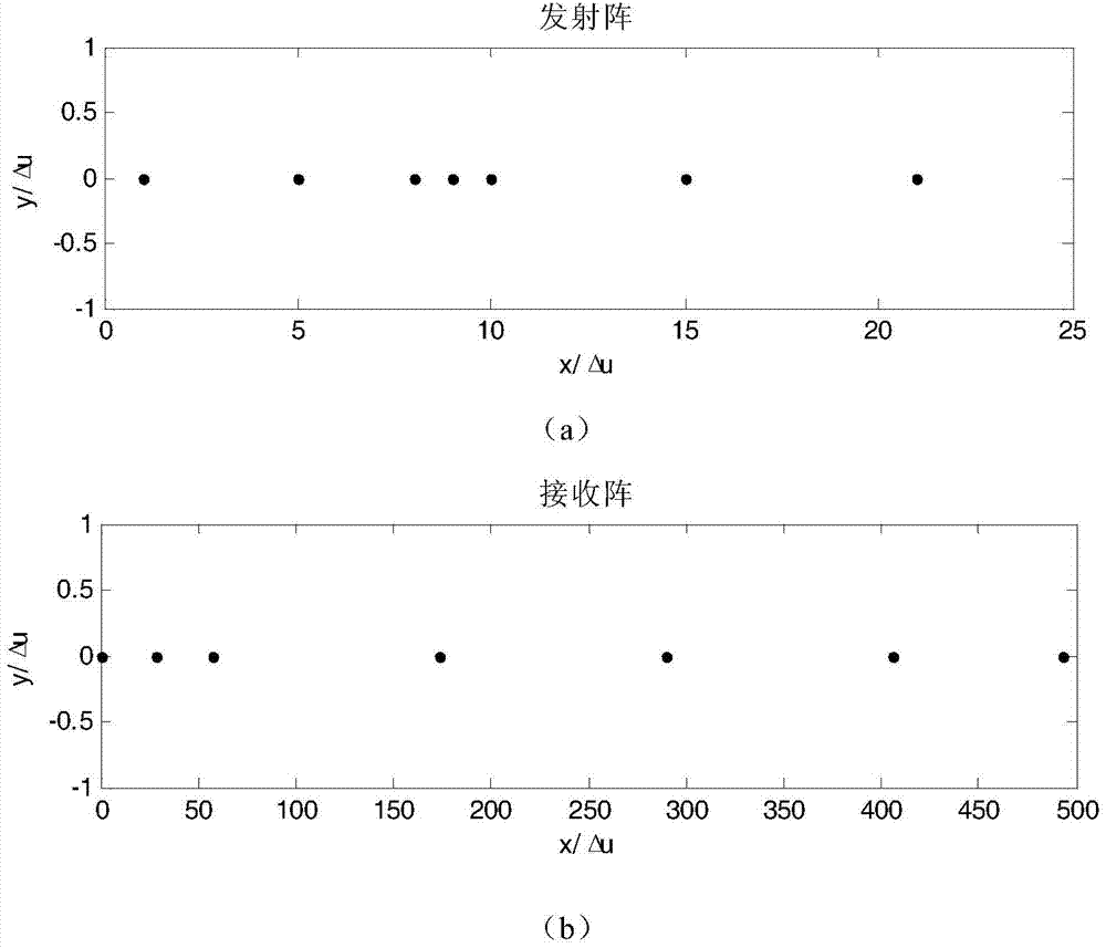
[0089] Given that the number of MIMO radar transmitting linear array elements is M=7, and the number of receiving linear array elements is N=7; set the minimum array element spacing Δu=0.5λ, and the positions of each array element are normalized by the minimum array element spacing . The parameters selected from the ADS library are (V, K, Λ, t)| K=M,Λ=1 The almost difference set of (when K=7, Λ=1, there is (29,7,1,14)-ADS in the library) as the initial almost difference set, that is m=1,2,...,7; select 7-element difference base B={b from difference set literature n}={0,1,2,6,10,14,17}, n=1,2,...,7.
[0090] Step 2. Construct the initial MR-MIMO array configuration
[0091] Let the initial launch array element position: Let the position of receiving array element: {u R,n}={b n 29}, such as figure 1 As shown; according to the working principle of MIMO radar, the array element position of the...
Embodiment 2
[0101] Step 1. Initialization of array parameters and almost difference sets
[0102] Given that the number of MIMO radar transmitting plane array elements is M x = M y =3, the number of receiving plane array elements is N x =N y =4; set the minimum array element spacing Δu x =Δu y =0.5λ, each array element position is normalized by the minimum array element spacing. When M=M x = M y = 3, Λ x =Λ y = 1, there exists in the library (V x , M x ,Λ x ,t x ) = (V y , M y ,Λ y ,t y )=(6,3,1,4) ADS, take this ADS as the initial almost difference set, that is mx=my=1,2,3; select 4-element difference base B={b from difference base literature nx}={b'ny}={0,1,4,6}, nx=ny=1,2,...,4.
[0103] Step 2. Construct MIMO radar transmitting planar array configuration
[0104] Let the emission plane array element position point set be: {u T,mx,my}={(d mx ,d' my )}, where {d mx}, {d' my} are respectively the optimal ADS collection determined according to the steps in claim ...
PUM
Abstract
The invention discloses a MIMOradarantenna array sparse arraying method, which is based on almost difference sets and difference bases, and establishes a MIMOradar transmitting / receiving array rapidly through enumeration shifting process. When all transmitting array elements transmit orthogonal signals simultaneously and receiving array elements receive echo signals simultaneously, a virtual array with even space can be established equivalently by utilizing a phase center approximation principle; number of the transmitting / receiving array elements is given, the continuous aperture maximization of the equivalent virtual array can be realized according to the MIMOradarantenna array sparse arraying method, thereby improving spatial resolution of a MIMO radarsystem significantly; and the continuous apertures of the virtual array are given, and the minimization of number of the transmitting / receiving array elements can be realized according to the MIMO radarantenna array sparse arraying method, thereby reducing hardware cost of the system significantly. The MIMO radar antenna array sparse arraying method has small computational complexity, and is applicable to establishment of MIMO radar sparse linear arrays and planar array.
Description
technical field [0001] The invention belongs to the technical field of radar array antennas, and relates to a method for sparsely arranging MIMO radar antenna arrays. Background technique [0002] As a new radar system, MIMO (Multiple Input Multiple Output) radar has received extensive attention in recent years. MIMO radar uses multiple antenna units at the transmitting end and receiving end at the same time, the transmitting end transmits their respective orthogonal waveforms, and each receiving unit uses a series of matched filters to extract these waveform signals, thereby equivalently synthesizing a large-aperture virtual receiving Array. Compared with traditional system radar, MIMO radar can greatly improve the spatial resolution of the system. [0003] Each element of the MIMO radar antenna array realizes the sampling of space electromagnetic waves. How to properly place the transmitting / receiving elements to obtain a virtual array with the best spatial sampling perf...
Claims
Application Information
Patent Timeline
Application Date:The date an application was filed.
Publication Date:The date a patent or application was officially published.
First Publication Date:The earliest publication date of a patent with the same application number.
Issue Date:Publication date of the patent grant document.
PCT Entry Date:The Entry date of PCT National Phase.
Estimated Expiry Date:The statutory expiry date of a patent right according to the Patent Law, and it is the longest term of protection that the patent right can achieve without the termination of the patent right due to other reasons(Term extension factor has been taken into account ).
Invalid Date:Actual expiry date is based on effective date or publication date of legal transaction data of invalid patent.

