Power conversion apparatus and buffer capacitor

A technology of power conversion device and buffer capacitor, which is used in capacitors, irreversible DC power input to convert AC power output, electrical components, etc., can solve problems such as secondary coil short circuit, and achieve the effect of reducing damping oscillations

Inactive Publication Date: 2015-08-19
MITSUBISHI ELECTRIC CORP
View PDF4 Cites 4 Cited by
  • Summary
  • Abstract
  • Description
  • Claims
  • Application Information

AI Technical Summary

Problems solved by technology

On the other hand, the secondary coil is short-circuited via a resistor

Method used


Image

  • Power conversion apparatus and buffer capacitor
  • Power conversion apparatus and buffer capacitor
  • Power conversion apparatus and buffer capacitor

Examples


Embodiment approach 1

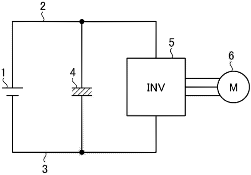
[0025] As an example of a power conversion device, consider an inverter for driving a motor. figure 1 It is a schematic diagram showing a motor drive device including an inverter.

[0026] Such as figure 1 As shown, a P-side power line 2 and an N-side power line 3 are respectively connected to the positive pole and the negative pole of the DC power supply 1 . A smoothing capacitor 4 is connected between the P-side power line 2 and the N-side power line 3 . As the smoothing capacitor 4, for example, an electrolytic capacitor is used. Furthermore, an inverter 5 is connected between the P-side power line 2 and the N-side power line 3 . Furthermore, an electric motor 6 serving as an inductive load is connected to an output end of the inverter 5 . The inverter 5 converts the DC voltage from the DC power supply 1 into a three-phase AC voltage through conversion, and outputs the three-phase AC voltage to the motor 6 . As a result, motor current flows through the motor 6, and the...

Embodiment approach 2

[0053] In Embodiment 2, the case where the above-mentioned conductor 60 (first conductor) on the current path 50 is a lead portion of the snubber capacitor 41 will be described.

[0054] Image 6 is an overall view showing the snubber capacitor 41 . The snubber capacitor 41 has a capacitor body 100 and a pair of pins 110 (110-1, 110-2). The pins 110 are used to connect the capacitor main body 100 and external wiring. More specifically, one of the pins 110-1 and 110-2 is connected to the P-side electric force line 2 (P-side electrode 12), and the other is connected to the N-side electric force line 3 (N-side electrode 13).

[0055] In this embodiment, the ringing reduction circuit 70 is connected to one or both of the pins 110-1 and 110-2. exist Figure 7 An example of a configuration for realizing the damping reduction circuit 70 as described above is shown.

[0056] First, the lead 110 is formed of a first conductor (hereinafter, the first conductor is also referred to a...

Embodiment approach 3

[0070] The conductor 60 (first conductor) on the current path 50 is not limited to the pin 110 of the snubber capacitor 41 . For example, conductor 60 may be electrodes (P-side electrode 12 , N-side electrode 13 ) of switching elements ( 21 , 31 ) in power module 10 . In this case, the ringing reduction circuit 70 is connected to one or both of the P-side electrode 12 and the N-side electrode 13 .

[0071] Figure 8 A circuit configuration in a case where the conductor 60 (first conductor) is the P-side electrode 12 of the power module 10 is schematically shown. Such as Figure 8 As shown, the ringing reduction circuit 70 is connected in parallel with the P-side electrode 12 . Thereby, the same effects as those of the foregoing embodiment are obtained.


PUM


Abstract

Damped vibration of a releasing current in a power conversion apparatus is alleviated. The power conversion apparatus comprises a switch element connected with an inductive load; a freewheel diode being in reverse parallel connection with the switch element; a first conductor located on a current path and connected with the switch element and the freewheel diode; and a damped vibration alleviating circuit being in parallel connection with the first conductor. The first conductor and the damped vibration alleviating circuit are electrically connected on a first contact and a second contact. The damped vibration alleviating circuit comprises a second conductor, a resistor and a capacitor which are connected between the first contact and the second contact in a parallel way. The second conductor is magnetically coupled to the first conductor between the first contact and the second contact.

Description

technical field [0001] The present invention relates to a power conversion device and a snubber capacitor. In particular, the present invention relates to a ringing power conversion device capable of reducing a recovery current, and a snubber capacitor applied to the power conversion device. Background technique [0002] In a power conversion device such as an inverter, generally, a transistor as a switching element and a freewheeling diode connected in antiparallel to the transistor are used. When a current flows through a freewheeling diode to which a forward bias is applied, if the bias is switched from forward to reverse, the current flows in the reverse direction. This phenomenon is called "recovery", and the current flowing through the diode at the time of recovery is called "recovery current". [0003] In this recovery current, an oscillation phenomenon called "ringing" sometimes occurs. The cause of the ringing is LC resonance caused by the parasitic inductance of...

Claims


Application Information

Patent Timeline
Patent Type & Authority Applications(China)
IPC IPC(8): H02M7/48H01G2/00
Inventor 田村静里
Owner MITSUBISHI ELECTRIC CORP
Why Eureka
Try Eureka