Auxiliary roller support device

An auxiliary support and roll technology, which is applied in the direction of keeping the roll equipment in an effective state, metal rolling, metal rolling, etc., can solve the problems of increasing the distance between the racks, reducing the yield of steel pipes, and bulky equipment, etc., to achieve Higher finish rolling temperature, lower maintenance cost, and shorter time

Inactive Publication Date: 2015-08-26
CISDI ENG CO LTD
View PDF7 Cites 0 Cited by
  • Summary
  • Abstract
  • Description
  • Claims
  • Application Information

AI Technical Summary

Problems solved by technology

During the rolling process, the rolling force is transmitted to the bearing seat through the bearing, and then transmitted to the hydraulic pressing system by the bearing seat. Due to the large rolling force, it is necessary to select a bearing with a larger diameter and width to ensure the life and strength of the bearing. In order to To avoid interference, it is necessary to select rolls with larger nominal diameters accordingly, which not only increases the rolling torque, but also increases the distance between stands, which in turn leads to a decrease in the steel pipe yield, a large equipment volume, and an increase in investment

Method used


Image

  • Auxiliary roller support device
  • Auxiliary roller support device

Examples


Embodiment 1

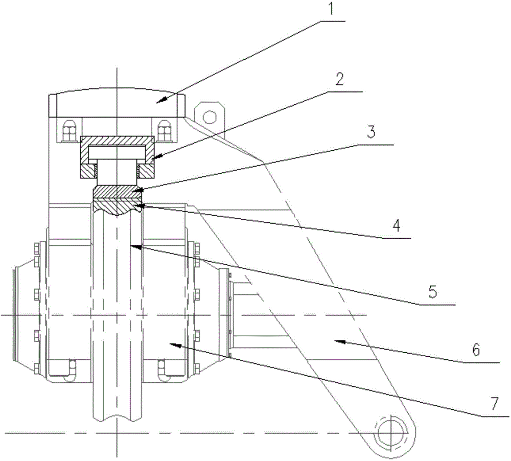
[0020] Such as figure 1 As shown, the roll auxiliary support device in this embodiment includes a pressing member and a pressing mechanism 2 for pressing the pressing member against the roll 5 . In this embodiment, the pressing part is a sliding block 4, the pressing mechanism 2 is a hydraulic cylinder, the sliding block 4 is slidingly matched with the roll 5, the sliding block 4 is installed on the hydraulic cylinder, and the sliding block 4 is tightly stretched out by the hydraulic cylinder. Press against the roll surface of roll 5. Of course, the depressing mechanism 2 can also be a screw jack or an electromagnet that repels each other, or even an electric push rod or an electric cylinder, as long as it can realize that the sliding block 4 is tightly pressed against the roller surface of the roll 5. .

[0021] Take the side swing roll gap adjustment mechanism as an example. The roll auxiliary support device is installed between the roll 5 and the pressure head 1, specifi...

Embodiment 2

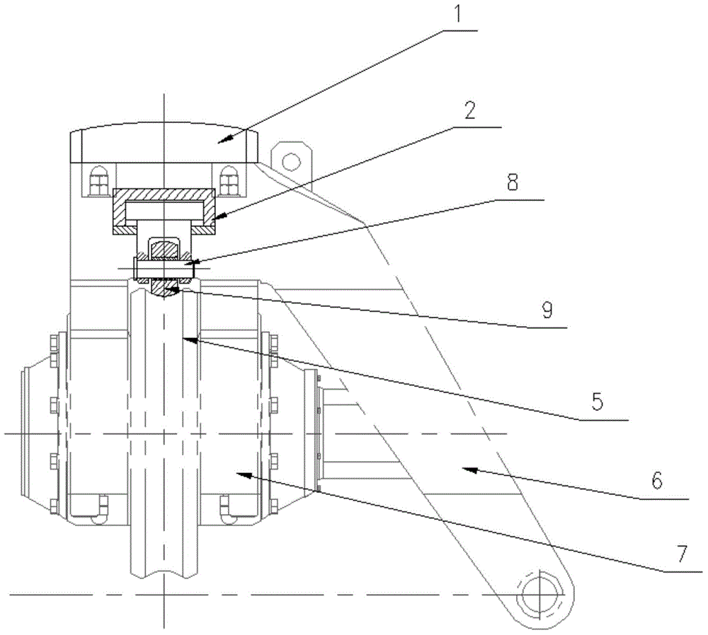
[0029] Such as figure 2 As shown, in this embodiment, the pressing member is a roller 9, and the roller 9 is sleeved on the connecting shaft 8 fixed on the pressing mechanism 2, and a bearing is provided between the roller 9 and the connecting shaft 8. Since the roller 9 and the roller 5 are in rolling fit, the wear of the roller 5 and the roller 9 is reduced, and the service life of the equipment is increased.


PUM


Abstract

The invention discloses an auxiliary roller support device. The auxiliary roller support device is composed of a pressing member and a downwards pressing mechanism for pressing the pressing member against the surface of a roller, wherein the pressing member is arranged on the downwards pressing mechanism; the downwards pressing mechanism tightly presses the pressing member against the roller to timely supplement the abrasive gaps formed between the pressing member and the roller and further to ensure effective support to the roller. By means of the auxiliary roller support device, roller bearings only bear a part of rolling force, so that the nominal diameter of the roller can be reduced, the dimension of an entire rolling machine transmission system comprising the auxiliary roller support device can be reduced, the vertical spacing of the diameter of every frame of the rolling machine can be reduced, the longitudinal dimension of the rolling machine can be more compact, the time of a piece to be rolled passing through the rolling machine can be shorter, the maintenance cost due to replacement of the transmission system can be reduced, and meanwhile, the effects of increasing the finish rolling temperature and shortening the length of out-of-tolerance parts of the wall thickness of head walls and end walls can be achieved.

Description

technical field [0001] The invention belongs to the field of rolling equipment for metal pipes or wire rods, and in particular relates to an auxiliary support device for rolls. Background technique [0002] At present, in the rolling production line, the rolling mill is the main deformation equipment, and the continuous rolling mill is generally equipped with several rolling stands, and the rolls are installed in the stands through bearings. During the rolling process, the rolling force is transmitted to the bearing seat through the bearing, and then transmitted to the hydraulic pressing system by the bearing seat. Due to the large rolling force, it is necessary to select a bearing with a larger diameter and width to ensure the life and strength of the bearing. To avoid interference, it is necessary to select rolls with larger nominal diameters accordingly, which not only increases the rolling torque, but also increases the distance between stands, which in turn leads to a d...

Claims


Application Information

Patent Timeline
IPC IPC(8): B21B28/00
Inventor 金强覃宣
Owner CISDI ENG CO LTD
Why Eureka
Try Eureka