Copper plating tank

A technology of copper plating and plating solution, applied in circuits, semiconductor devices, etc., can solve the problems of uneven thickness of circuit board plating, aggravate workpiece edge effects, etc., and achieve the effect of improving electroplating efficiency and uniformity

Active Publication Date: 2015-08-26
江新德
View PDF9 Cites 13 Cited by
  • Summary
  • Abstract
  • Description
  • Claims
  • Application Information

AI Technical Summary

Problems solved by technology

However, the setting of the baffle aggravates the edge effect of the workpiece (electroplating cathode) to a certain extent.
[0009] (3) A centralized anode is adopted, that is, a whole piece of anode with a larger area can achieve uniform distribution of electric power lines to a certain extent in the area facing the anode, but there are still dense electric force lines at the edge of the anode, so there are also edge The effect will cause the thickness of the plating at both ends of the board to be different

Method used


Image

  • Copper plating tank
  • Copper plating tank
  • Copper plating tank

Examples


Embodiment Construction

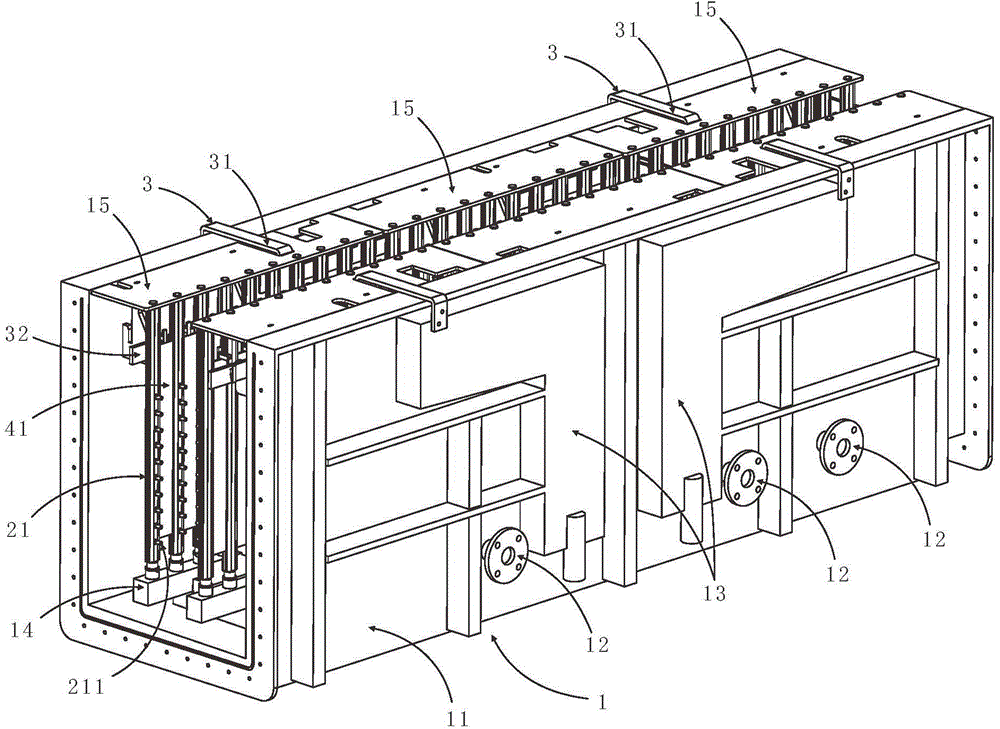
[0040] Such as figure 1 As shown, the copper plating tank of the present invention includes a tank body 1, a nozzle array located in the tank body 1, an anode hanger 3, and an anode array, wherein:

[0041] The tank 1 is used to accommodate the electroplating solution, and is composed of a U-shaped tank unit 11; the side wall of the U-shaped tank unit 11 has at least one plating solution inlet pipe 12, and at least one plating solution overflow recovery device 13; The plating solution inlet pipe 12, the plating solution overflow recovery device 13 are in communication with the plating solution circulation system (not shown) outside the tank body 1; According to the needs, a plurality of U-shaped tank units 11 can also be sequentially connected to form a longer tank;

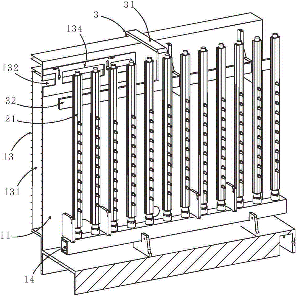
[0042] Nozzle arrays, such as figure 2 As shown, there are a plurality of nozzles 21 side by side, the top of the nozzles 21 is sealed, the bottom of the nozzles 21 communicates with the plating solution inlet...


PUM


Abstract

The invention discloses a copper plating tank. The copper plating tank comprises a tank body, a spraying pipe array arranged in the tank body, anode hangers and an anode array, wherein the tank body is used for accommodating an electroplating solution and consists of a U-shaped tank body unit or a plurality of the U-shaped tank body units connected in sequence; the spraying pipe array is provided with a plurality of spraying pipes arranged side by side, a plurality of spray nozzles for spraying a plating solution are arranged on the front surface of each of the spraying pipes in the height directions of the spraying pipes, and shielding grooves are formed in two side edges of the spraying pipes; the anode hangers are used for supplying anode currents and comprise conductive flat plates arranged in the length direction of the U-shaped tank body unit; the anode array is provided with a plurality of anode monomers, anode strips immersed in the electroplating solution are arranged at the lower parts of the anode monomers, and the left lateral edges and the right lateral edges of the anode strips are inserted into shielding grooves between every two adjacent spraying pipes. According to the copper plating tank disclosed by the invention, the distribution of electric power lines in the plating solution can be effectively improved, so that an edge effect is eliminated; the electric currents which do not exceed the upper limit of current density can also be effectively supplied, so that the uniformity of a copper layer is improved, and the electroplating efficiency is improved; the copper plating tank is suitable for various printed circuit boards such as a back board, a base board, and a flexible board .

Description

technical field [0001] The invention relates to a copper plating bath, which is especially suitable for a continuous electroplating production line for copper plating of printed circuit boards. Background technique [0002] The uniformity of the surface coating thickness of the printed circuit board directly affects the important indicators of the subsequent processing technology of the printed circuit board. Fine lines; For packaging substrates, good plating thickness with uniformity can obtain reliable soldering performance to improve yield. [0003] The uniformity of the surface coating thickness of the printed circuit board is limited by the plating current and is also affected by the edge effect (point effect). [0004] Any plating solution has a current density range to obtain a good coating, the minimum current density to obtain a good coating is the lower limit of the current density, and the maximum current density to obtain a good coating is the upper limit of the...

Claims


Application Information

Patent Timeline
Patent Type & Authority Applications(China)
IPC IPC(8): C25D19/00C25D7/12
Inventor 江新德舒迎春
Owner 江新德
Why Eureka
Try Eureka