Large-structure sublevel drilling stage ore removal mining method with delayed filling

A filling mining method and a large-scale structure technology, which is applied in the direction of filling, ground mining, mining equipment, etc., can solve the problems of large cutting engineering, waste of ore resources, and large consumption of personnel and equipment, and achieve production scheduling and management. Simple, solve the effect of high engineering maintenance costs and low labor intensity

Active Publication Date: 2015-08-26
CHINA MINMETALS CHANGSHA MINING RES INST +1
View PDF6 Cites 19 Cited by
  • Summary
  • Abstract
  • Description
  • Claims
  • Application Information

AI Technical Summary

Problems solved by technology

[0004] For large and extra-large underground mines, the above-mentioned structural parameters are used for production by the segmented rock drilling stage and then filling method. In order to meet the production capacity of the mine, it is often necessary to arrange multiple middle sections and multiple stopes for simultaneous production. Accurate cutting has a large amount of work and a tight construction period. The workload of production scheduling and operation arrangement in the stope is complicated. The consumption of personnel and equipment and work shifts is large, and the work efficiency is low.
In addition, if the bottom structure is not recovered, a considerable part of the ore resources will be wasted and lost; if the recovery is completed in the middle section or at the end of the service life, the original part of the project needs high maintenance costs, and is affected by the early mining and the special occurrence of bottom structure ores. Influenced by shape, the recovery environment deteriorates seriously in the later stage, and the layout and construction of new projects are difficult

Method used


Image

  • Large-structure sublevel drilling stage ore removal mining method with delayed filling
  • Large-structure sublevel drilling stage ore removal mining method with delayed filling
  • Large-structure sublevel drilling stage ore removal mining method with delayed filling

Examples


Embodiment Construction

[0023] The present invention will be further described below in conjunction with the accompanying drawings and specific embodiments.

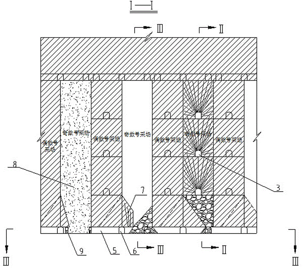
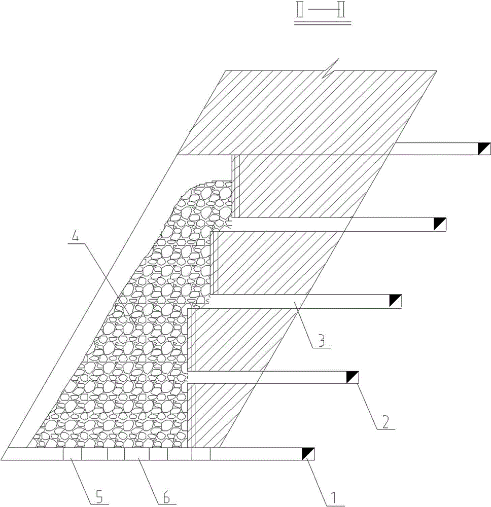
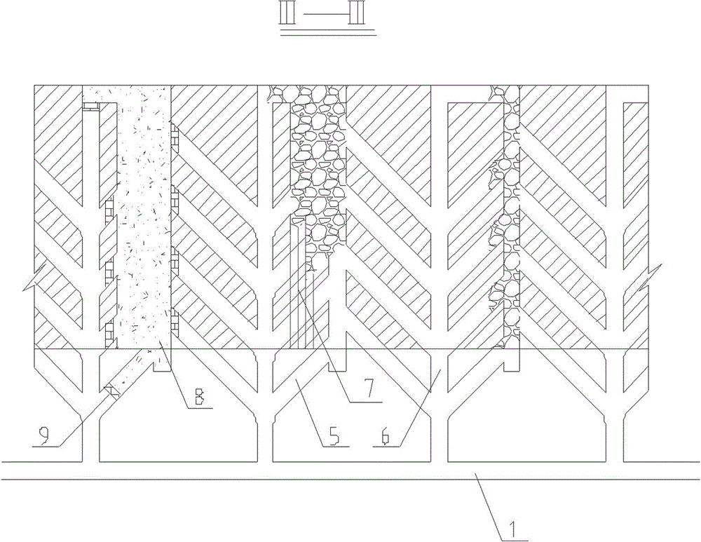
[0024] see figure 1 , figure 2 , image 3 and Figure 4 , the ore body is divided into odd-numbered stopes and even-numbered stopes along the strike, and according to the structural parameters of the middle section height of 100m, the stope span of 20m, and the section height of 25m, the middle section of the transportation roadway, segmented roadway, chisel Mining and cutting projects such as rock roadway, ore-piercing vein, ore-exit approach. Mining can begin after the mining and cutting works are completed. During mining, the first step is to mine the odd-numbered stopes, and the gobs will not be filled; the second step is to mine the 1 / 2 bottom structure corresponding to the odd-numbered stopes. goaf and its bottom structure; in the third step, the even-numbered stope is mined, and the goaf is not filled; in the fourth step, the other ...


PUM


Abstract

The invention relates to a large-structure sublevel drilling stage ore removal mining method with delayed filling. The mining method comprises stoping in stopes and bottom structure recovery which are carried out synchronously in a crossed manner, and comprises the following steps: step 1, stoping in odd-numbered stopes, wherein the stoping manner is sublevel drilling stage ore removal, and mined out space I is not filled immediately; step 2, stoping in 1/2 bottom structures I corresponding to the odd-numbered stopes, and filling ore rooms and the mined out space I, corresponding to the 1/2 bottom structures I, of the ore rooms after stoping is finished; step 3, stoping in even-numbered stopes, wherein mined out space II is not filled immediately; step 4, stoping in 1/2 bottom structures II corresponding to ore pillars, and filling the ore pillars and the mined out space II, corresponding to the 1/2 bottom structures II, of the ore pillars after stoping is finished. The mining method has the advantages that the mining-cutting work amount is reduced greatly; the production capacity of a single stope is high; the efficiency is high; workers' labor intensity is low; production, dispatching and management are simple. Moreover, stoping of the main ore in a stope and recovery of ore in the bottom structure of the stope are realized synchronously in a crossed manner, and the stoping operation is safe, so that the resource recovery rate is high.

Description

technical field [0001] The invention belongs to the field of underground mining, and in particular relates to a large-structure segmental rock-drilling stage mining method followed by filling mining for the mining of stable and steeply inclined thick ore bodies. Background technique [0002] For the mining of steeply inclined thick and large ore bodies with stable to extremely stable rocks, the mining method of segmental rock drilling and subsequent filling is a more suitable mining method. In this method, the ore body in the middle section is divided into sections, and the bottom level of the stage is equipped with a bottom ore discharge structure. In the segmental rock drilling roadway, rock drilling, blasting and ore dropping are carried out, and the collapsed ore is concentrated at the bottom ore discharge level for shoveling or transportation. The mined-out area shall be filled after the stope falling and mining are completed. [0003] At present, the stage height of t...

Claims


Application Information

Patent Timeline
Patent Type & Authority Applications(China)
IPC IPC(8): E21C41/22E21F15/00
CPCE21C41/22E21F15/00
Inventor 宋嘉栋周爱民林卫星詹进周礼柳小胜欧任泽王长军甯瑜林宋兴罗佳
Owner CHINA MINMETALS CHANGSHA MINING RES INST
Why Eureka
Try Eureka