radial centrifugal turbine

A radial centrifugal and turbine technology, applied in the direction of preventing leakage, supporting elements of blades, stators, etc., can solve the problems of increasing system instability, generating large vibration, and small air intake flow, and improving work efficiency, The effect of avoiding vibration and increasing the intake air volume

Inactive Publication Date: 2017-03-08
UNIV OF SHANGHAI FOR SCI & TECH
View PDF1 Cites 0 Cited by
  • Summary
  • Abstract
  • Description
  • Claims
  • Application Information

AI Technical Summary

Problems solved by technology

[0006] Existing radial flow centrifugal turbines are all in the form of one-way suction cantilever, so they have a large axial force and a small intake flow; there is a gap between the top of the blade and the wall of the centrifugal turbine, which will cause gap loss; Only one end of the rotor blade and stator blade of the centrifugal turbine is fixed, and the other end is exposed, which will generate large vibration during the rotation process and increase the instability of the system

Method used


Image

  • radial centrifugal turbine
  • radial centrifugal turbine
  • radial centrifugal turbine

Examples


Embodiment Construction

[0021] The radial centrifugal turbine involved in the present invention will be described in detail below with reference to the accompanying drawings.

[0022]

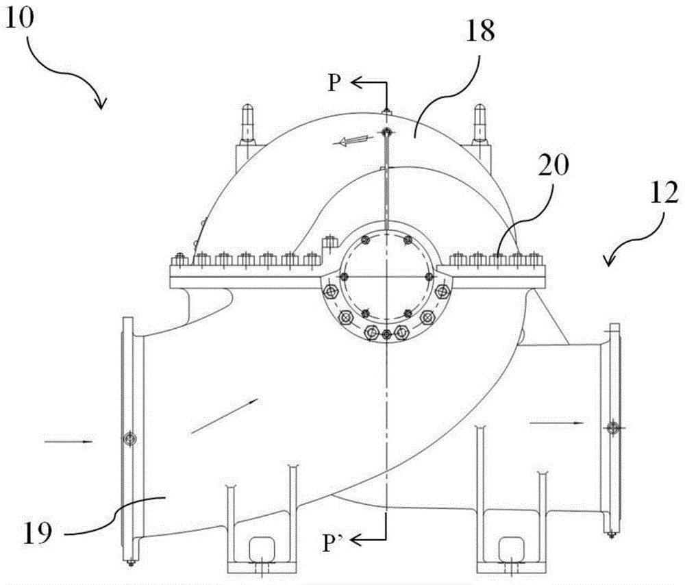
[0023] figure 1 is a schematic structural view of the radial centrifugal turbine of the embodiment;

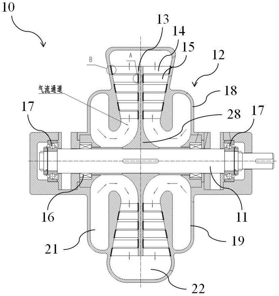
[0024] figure 2 yes figure 1 The cross-sectional view of the P-P' direction.

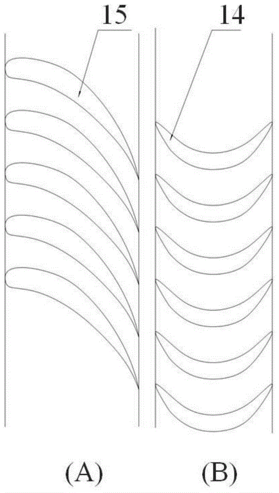
[0025] Such as figure 1 , 2 As shown, the radial centrifugal turbine 10 includes a rotating shaft 11 , a casing 12 , a disc 13 , multiple sets of moving blade cascades 14 , multiple sets of stationary blade cascades 15 and a sealing body 16 .

[0026] The rotating shaft 11 is rotatably fixed on the bearings 17 at both ends, and rotates under the drive of the wheel disc 12, and the rotating shaft 15 is connected to a generator or other working machines (not shown in the figure).

[0027] The housing 12 serves to protect the radial centrifugal turbine 10 . In this embodiment, the casing 12 includes an upper casing 18 and a lower cas...


PUM


Abstract

The invention provides a radial centrifugal turbine which is characterized by comprising a rotating shaft in axial symmetry, a housing, a wheel disc in axial symmetry, a plurality of groups of movable vanes in axial symmetry, a plurality of groups of static vanes in axial symmetry and a sealing body, wherein the rotating shaft is used for fixing the wheel disc and is driven by the wheel disc to rotate; the housing comprises a double-air-intake prerotation volute and an air-outlet volute; the wheel disc can rotate around a central shaft; each of the plurality of groups of movable vanes is arranged on the corresponding circumference of the wheel disc, one ends of the movable vanes are fixed on the wheel disc, and the other ends of the movable vanes are rotatably embedded into the housing d through movable vane enclosing bands, and the wheel disc is driven by the movable vanes to rotate under the action of the air flow; one ends of the plurality of groups of static vanes are fixed on the housing, and the other ends of the static vanes are rotatably embedded into the wheel disc through static vane enclosing bands; the sealing body is arranged between the rotating shaft and the housing and used for preventing air flow leakage; the movable vanes and the static vanes are alternatively arranged in the radial direction of the rotating shaft; the one nearest to the rotating shaft is one group of static vanes; movable blades of the movable vanes and static blades of the static vanes are straight blades, and the shapes of the cross sections of the straight blades in the blade height direction are not changed.

Description

technical field [0001] The invention relates to the field of thermal generators or power machinery, in particular to a two-way suction multistage radial centrifugal turbine. Background technique [0002] There are two types of turbines, axial flow and radial flow. [0003] Now commonly used radial flow turbines are all centripetal, and there are also a small amount of centrifugal radial turbines, such as the disclosed radial centrifugal turbine of utility model CN203809056U. Radial centrifugal turbine is a newly developed small thermal generator, which is often used in waste heat power generation, geothermal power generation, solar power generation, automobile turbocharging, etc. [0004] Due to the different linear speeds of rotation at different radial positions in existing axial flow turbines, twisted blades must be used. Even if the design is good, for long blades, there is still a large change in the degree of reaction from the root to the top. From the root to the top...

Claims


Application Information

Patent Timeline
Patent Type & Authority Patents(China)
IPC IPC(8): F01D1/06F01D25/24F01D5/14F01D9/02F01D5/16F01D11/08
Inventor 黄典贵谭鑫李银各
Owner UNIV OF SHANGHAI FOR SCI & TECH
Why Eureka
Try Eureka