A high-precision rubber ball monitoring device

A monitoring device, high-precision technology, applied in the direction of cleaning heat transfer devices, non-rotating equipment cleaning, lighting and heating equipment, etc., can solve the problems of high labor intensity, mechanical wear, counting errors, etc., to reduce labor intensity and occupy an area The effect of less space and easier shaping

Active Publication Date: 2017-03-01
SHENYANG INST OF ENG
View PDF11 Cites 0 Cited by
  • Summary
  • Abstract
  • Description
  • Claims
  • Application Information

AI Technical Summary

Problems solved by technology

However, in the actual production process, due to the impurities in the circulating water, the dead angle of the system or the defects of the rubber ball itself, the ball collection rate often fails to meet the requirements of the unit; according to the needs, the rubber ball monitoring link becomes an indispensable part of the condenser of the power station. part
[0003] Common rubber ball monitoring methods are: (1) Manual periodic inspection method: This method takes a long time to detect and is labor-intensive, and is not suitable for use in units with frequent rubber ball cleaning. Many power plants still use this method; (2) Mechanical counting method: the principle of this method is that when the rubber ball passes through the monitoring device, the transmission mechanism in the device is toggled, and then the cumulative calculation function is realized; such as Chinese patent CN201210216321.6 The title "A rubber ball counting device for use on a rubber ball cleaning device" refers to such a device
This kind of equipment is easy to cause mechanical wear after long-term operation; (3) Image analysis method: In this monitoring process, a high-speed camera is installed to take pictures of the rubber balls passing through the monitoring window, and then implement image analysis technology, and finally realize the rubber ball The purpose of counting; as in "Energy Conservation" (No. 2, 2008, pages 29-32), it is exactly such a device that is involved in the "Automatic Monitoring Device for Condenser Rubber Ball Cleaning"; but this This method requires complex image analysis techniques, and counting errors can also occur when the glue balls overlap. More importantly, this device requires a relatively large transparent window on the pipe, which is likely to cause the pipe (4) Acousto-optic switch method: This method is currently the most used method, which uses ultrasonic waves or light to count the on-off when the rubber ball passes; for example, the Chinese patent CN200910010097.3 is named "On-line monitoring device for rubber ball cleaning of power plant condenser based on optical fiber sensor technology" involves exactly such a monitoring method; The disadvantage of the low accuracy of the general acousto-optic switch rubber ball monitoring equipment is that the rubber ball monitoring device that uses the shunt parts to disperse the rubber balls to each monitoring pipeline improves the accuracy of the rubber ball monitoring; however, in the actual production process, the rubber balls are recycled. The speed is very fast, and the ball collection rate can reach more than 90% after 5 minutes; in some units with a large amount of rubber balls, some rubber balls will pass through the monitoring sensor continuously during cleaning, and the above monitoring device will It is easy to cause misjudgment of counting and even blockage. Therefore, a new high-precision rubber ball monitoring device is proposed

Method used


Image

  • A high-precision rubber ball monitoring device
  • A high-precision rubber ball monitoring device
  • A high-precision rubber ball monitoring device

Examples


Embodiment Construction

[0021] Combine below Figure 1~6 The specific structure and working engineering of the present invention are described in detail, and the description in the drawings is exemplary, and is only used to explain the present invention, but not to be construed as a limitation of the present invention.

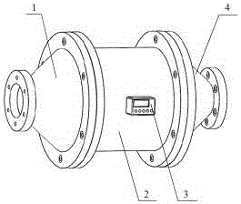
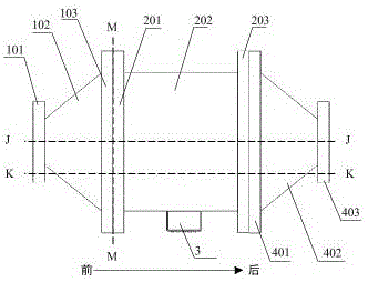
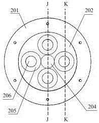
[0022] The rubber ball monitoring device includes the following parts: expansion chamber 1, diversion chamber 2, control display 3, diameter reduction chamber 4, multiple photoelectric sensors 301, multiple flow sensors 302 and connection control display 3, photoelectric sensor 301 and flow sensor 302 electrical connection wire (not marked in the figure).

[0023] The expansion chamber 1 is used to connect the circulating water pipeline 8 and the distribution chamber 2, including the expansion chamber inlet flange 101, the expansion chamber cover 102 and the expansion chamber outlet flange 103; wherein the expansion chamber inlet flange 101 is connected to the circulation The water ...


PUM


Abstract

In several units with large rubber ball using amount, certain rubber balls continuously pass through a monitoring sensor during systematic cleaning, mistaken counting judgment easily occurs at the moment, or even a blockage phenomenon occurs. For solving the problem, the invention provides a novel high-precision rubber ball monitoring device. Firstly, under the effect of a distribution bin, rubber balls running in a circulating water pipeline are distributed to multiple front distribution flowing channels. Under the acceleration effect of the circular truncated cone shaped front distribution flowing channels, separation of the rubber balls falling into the front distribution flowing channels are accelerated to a rear distribution flowing channel provided with a photoelectric sensor and a flow sensor. The number of passed rubber balls is corrected through reasonable analysis on the actual passing time of the rubber balls and the passing time of a single rubber ball, accordingly the purpose of online rubber ball monitoring is achieved, and the labor intensity of workers in a field is greatly reduced. In addition, the novel high-precision rubber ball monitoring device further has the remarkable advantages of being low in cost, relatively simple in structure, convenient to cast, easy to form, small in occupied space, low in power consumption and the like.

Description

technical field [0001] The invention relates to an online operating device for monitoring the number of cleaning rubber balls on a circulating water pipeline of a condenser of a power station, belongs to the technical field of mechanical and electronic device design, and can also be applied to other related or similar occasions. Background technique [0002] The condenser is one of the important components of the steam turbine unit and an important part of the power thermal cycle, which has a decisive impact on the safety and economic operation of the entire thermal power plant; according to the cooling method, the condenser can be divided into water-condensing steam Condensers and air-cooled condensers, among which water-cooled condensers are widely used in modern power plants. However, due to factors such as circulating water quality and temperature, various degrees of dirt will appear on the inner wall of the condenser pipe, resulting in reduced unit vacuum, reduced heat ...

Claims


Application Information

Patent Timeline
Patent Type & Authority Patents(China)
IPC IPC(8): F28G1/12F28G15/00
Inventor 李智王圣毫裴振英赵殿瑞曹予维王勇
Owner SHENYANG INST OF ENG
Why Eureka
Try Eureka