
Dynamic calibration and correction method for fixed errors of NMOS linear array image sensor system

A technology of fixed error and linear array image, applied in the field of dynamic calibration and correction of fixed error of NMOS linear array image sensor system, can solve the problems of hardware zero adjustment period and frequency being difficult to grasp, and the effect is not ideal, so as to overcome the difficulty of period and frequency. Grasp, improve accuracy, reduce the effect of design

Inactive Publication Date: 2015-08-26
CHANGCHUN INST OF OPTICS FINE MECHANICS & PHYSICS CHINESE ACAD OF SCI
View PDF3 Cites 0 Cited by
  • Summary
  • Abstract
  • Description
  • Claims
  • Application Information

AI Technical Summary

Problems solved by technology

[0007] In order to solve the existing correction methods for system fixed errors of NMOS line array image sensors and their external readout circuits, they all focus on each error source, and take measures from the system design or the working environment of the image sensor, in order to reduce them one by one and individually. Their error output level can further reduce the superposition or accumulation of these errors in the overall fixed error of the system, but these traditional error correction methods have limitations, and the effect is not ideal, and the cycle and frequency of hardware zeroing are not easy to grasp. At present, there is no technical problem of performing overall mathematical modeling based on real-time measurement results for the system fixed error output by the NMOS line array image sensor and its external readout circuit, and solving and correcting the system fixed error accordingly. The present invention Provide a dynamic calibration and correction method for fixed errors of NMOS line array image sensor system

Method used


Image

  • Dynamic calibration and correction method for fixed errors of NMOS linear array image sensor system
  • Dynamic calibration and correction method for fixed errors of NMOS linear array image sensor system
  • Dynamic calibration and correction method for fixed errors of NMOS linear array image sensor system

Examples


Embodiment Construction

[0046] The present invention will be described in further detail below in conjunction with the examples.

[0047] A method for dynamically calibrating and correcting fixed errors of an NMOS line array image sensor system according to the present invention includes the following steps:

[0048] Step 1. Carry out overall mathematical modeling of the system fixed error of the NMOS line array image sensor and its external readout circuit, the specific method is:

[0049] According to the relationship between the system fixed error and the integration time, the mathematical model of the system fixed error of the NMOS line array image sensor and its external readout circuit is expressed as:

[0050] E=E R +T×E D (1)

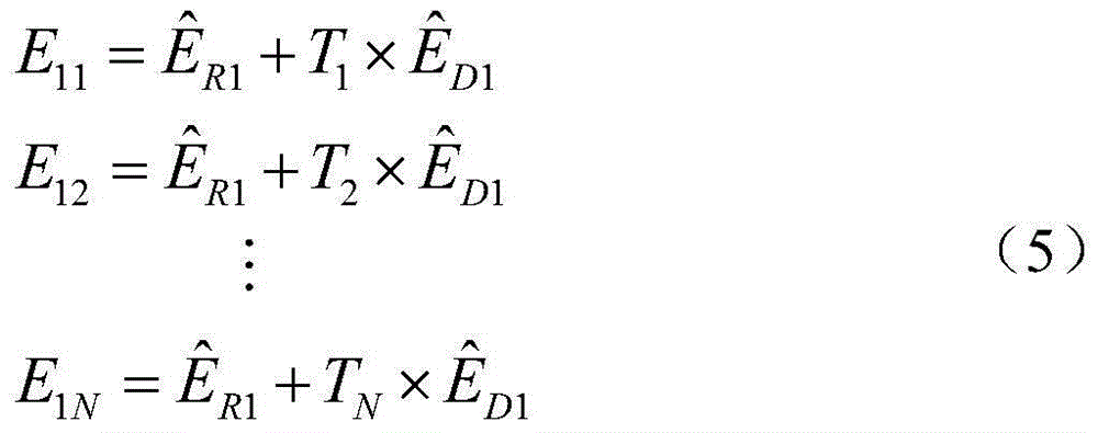
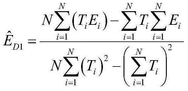
[0051] In formula (1), E represents the total amount of system fixed errors of the NMOS linear image sensor and its external readout circuit, T is the integration time (in seconds), and E D Indicates the cumulative amount of the fixed error that changes with the ...


PUM


Abstract

A dynamic calibration and correction method for fixed errors of an NMOS linear array image sensor system belongs to the field of an error correction method for a linear array image sensor system. The dynamic calibration and correction method cause a fact that various errors of the NMOS linear array image sensor and an outer read-out circuit are divided to a variable portion which is proportional with an integration time and a constant portion. Furthermore a mathematical model with a fixed system error is established based on the fact. An error real-time measurement test for the image sensor is designed. According to an actual measurement result, the dynamic calibration and correction method with the fixed error based on the model is established. The dynamic calibration and correction method abandons traditional measures which aim at various error sources and are at aspects of system hardware design or image sensor working environment, thereby changing a long-period and high-cost processing manner with a fixed error in the measurement result.

Description

technical field [0001] The invention belongs to the field of error correction methods for line array image sensor systems, and in particular relates to a dynamic calibration and correction method for fixed errors of NMOS line array image sensor systems. Background technique [0002] NMOS line array image sensor is a sensor for light signal energy measurement. It has the advantages of large dynamic range, high signal-to-noise ratio, small dark current, wide spectral response range and low power consumption. It is very suitable for weak light signals and precise spectra. The rapid measurement of signals has been widely used in ground spectroscopic instruments and aerospace spectroscopic measurement equipment. The NMOS line array image sensor has a large pixel size and a large dynamic range, so it can integrate the spectral signal for a long time and improve the detection sensitivity. Companies that produce NMOS linear image sensors, such as Hamamatsu HAMAMATSU in Japan and RE...

Claims


Application Information

Patent Timeline
IPC IPC(8): G01J3/28
Inventor 张佩杰宋克非
Owner CHANGCHUN INST OF OPTICS FINE MECHANICS & PHYSICS CHINESE ACAD OF SCI
Learn More