Optical projection tomography detection method

A technology of optical projection tomography and detection methods, which is applied in the direction of material analysis, measuring devices, scientific instruments, etc. through optical means, and can solve the problems of increasing experimental complexity and insufficient research

Active Publication Date: 2015-08-26
INST OF AUTOMATION CHINESE ACAD OF SCI
View PDF6 Cites 2 Cited by
  • Summary
  • Abstract
  • Description
  • Claims
  • Application Information

AI Technical Summary

Problems solved by technology

At the same time, the process of adding fluorescent labels to the sample will increase the complexity of the experiment, and how to make the fluorescent substance fully and specifically bind to the specific tissue of the large-volume sample is still insufficiently studied.

Method used


Image

  • Optical projection tomography detection method
  • Optical projection tomography detection method
  • Optical projection tomography detection method

Examples


Embodiment Construction

[0020] The detection method of the optical projection tomography provided by the embodiment of the present invention will be described in detail below with reference to the accompanying drawings.

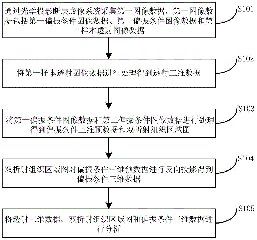
[0021] figure 1 It is a flow chart of the detection method of optical projection tomography provided by the embodiment of the present invention.

[0022] refer to figure 1 , in step S101, first image data is collected by an optical projection tomography system, and the first image data includes first polarization condition image data, second polarization condition image data and first sample transmission image data.

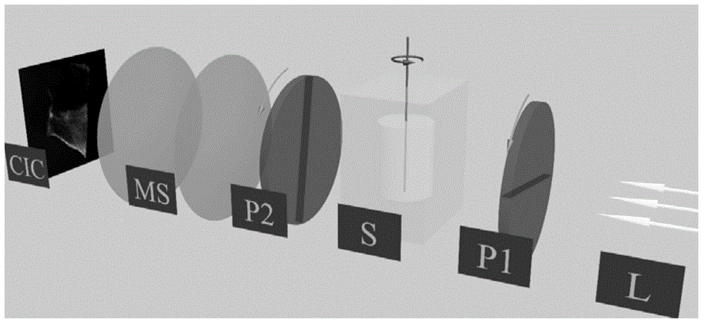
[0023] Here, the optical projection tomography system includes a light source module and a signal acquisition module. The light source module includes a light source, frosted glass, and adjustable polarizer; the signal acquisition module includes a microscope group, a camera, and an adjustable polarizer. For details, refer to figure 2 The schematic diagram of the o...


PUM

PropertyMeasurementUnit
angleaaaaaaaaaa

Abstract

The invention provides an optical projection tomography detection method. The method comprises acquiring first image data through an optical projection tomography imaging system, wherein the first image data comprises first polarization condition image data, second polarization condition image data and first sample transmission image data; processing the first sample transmission image data to obtain transmission three-dimensional data; processing the first polarization condition image data and the second polarization condition image data to obtain polarization condition three-dimensional pre-data and a birefringence tissue region graph; performing back projection on the polarization condition three-dimensional pre-data through the birefringence tissue region graph to obtain polarization condition three-dimensional data; analyzing the transmission three-dimensional data, the birefringence tissue region graph and the polarization condition three-dimensional data. By the aid of the method, birefringence tissues in an optical projection tomography imaging system can be detected effectively.

Description

technical field [0001] The invention relates to optical projection tomography technology, in particular to a detection method of optical projection tomography. Background technique [0002] Optical projection tomography can be divided into transmission optical projection tomography and excitation optical projection tomography, both of which take advantage of the characteristic that light propagates approximately along a straight line in a transparentized subcentimeter-sized biological sample. Among them, the transmission optical projection tomography technology uses a light source to emit visible light to penetrate the sample, and then uses a camera to collect projection views of the sample from multiple angles for three-dimensional imaging; while the excitation optical projection tomography technology uses laser light to irradiate fluorescent substances in the sample , the fluorescent substance emits emission light after receiving the excitation light, and a camera is used ...

Claims


Application Information

Patent Timeline
Patent Type & Authority Applications(China)
IPC IPC(8): G01N21/23
Inventor 田捷方梦捷董迪惠辉杨鑫徐敏
Owner INST OF AUTOMATION CHINESE ACAD OF SCI
Why Eureka
Try Eureka