Multi-channel multi-sub-band sliding-spotlight-mode SAR imaging method

A sliding beamforming and multi-channel technology, applied in the direction of radio wave reflection/re-radiation, using re-radiation, measuring devices, etc., can solve the problem that MIMO-SAR is difficult to achieve two-dimensional high resolution at the same time, and it is difficult to achieve azimuth reconstruction and frequency band synthesis, and the inability to effectively realize high-resolution wide mapping band SAR imaging, etc., to avoid huge calculations and achieve the effect of effective sub-band signal synthesis

Inactive Publication Date: 2015-08-26
XIDIAN UNIV
View PDF3 Cites 38 Cited by
  • Summary
  • Abstract
  • Description
  • Claims
  • Application Information

AI Technical Summary

Problems solved by technology

However, the change of beam orientation leads to a sharp increase in the bandwidth of its bearing signal, which is usually much larger than the sampling frequency PRF, so the bearing signal is usually aliased
This makes it impossible to obtain alias-free images using conventional imaging methods, range Doppler algorithms, frequency modulation scaling algorithms, and range migration algorithms.
One method of anti-aliasing is to increase the sampling frequency PRF during system design. However, a large sampling frequency PRF will greatly increase the amount of azimuth data, and it is also easy to cause problems such as distance ambiguity and limited data downloading.
[0004] In order to obtain a wide mapping zone, the research on multi-input and multi-receive MIMO-SAR technology is currently being carried out at home and abroad. It is difficult for MIMO-SAR to achieve two-dimensional high resolution at the same time.
In order to meet the two requirements of high resolution and wide swath of SAR imaging results at the same time, it is necessary to combine the sliding beamforming mode with MIMO-SAR technology. However, it is difficult to achieve azimuth reconstruction because the rotation of the antenna beam will increase the azimuth frequency band. and frequency band synthesis, so that SAR imaging with high resolution and wide mapping band cannot be effectively realized

Method used


Image

  • Multi-channel multi-sub-band sliding-spotlight-mode SAR imaging method
  • Multi-channel multi-sub-band sliding-spotlight-mode SAR imaging method
  • Multi-channel multi-sub-band sliding-spotlight-mode SAR imaging method

Examples


Embodiment Construction

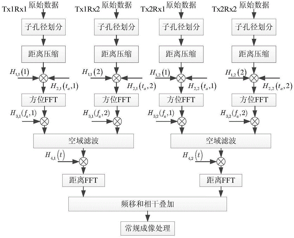
[0027] refer to figure 1 , the present invention processes the imaging steps of SAR data as follows:

[0028] Step 1. Divide the antenna of the stepped frequency multi-channel synthetic aperture radar SF-MIMO-SAR into sub-apertures; and perform the error compensation of the equivalent phase center of the multi-channel antenna and the range-oriented pulse compression on the echoes received by each sub-aperture in turn ;

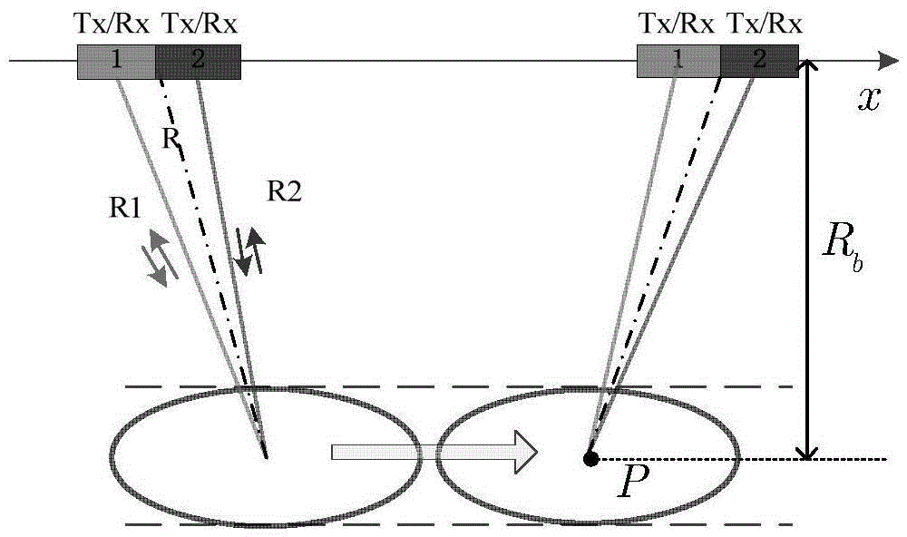
[0029] 1a) Refer to figure 2 , assuming that the number of array elements of the transmitting array and the number of array elements of the receiving array are both N, according to the different positions of the sending and receiving sides X n and x m , calculate the equivalent phase center position of the two: X′ nm =(X n +X m ) / 2;

[0030] Among them, X n is the position of the nth transmitting element, n=1,2,...,N; X m is the position of the mth receiving array element, m=1,2,...,N, N is an integer greater than zero;

[0031] 1b) For the differen...


PUM


Abstract

The invention discloses a multi-channel multi-sub-band sliding-spotlight-mode SAR imaging method. With the method, a problem of difficult orientation reconstruction and frequency band synthesis of the step-frequency multi-channel synthetic aperture radar under the sliding spotlight mode can be solved. The method is implemented by the following steps: firstly, carrying out sub aperture division on a multi-channel antenna and carrying out equivalent phase center error compensation and range direction pulse compression successively on an echo received y each sub aperture; secondly, carrying out doppler shift operation on the signal after the range direction pulse compression and moving the doppler shift to a doppler base band; thirdly, calculating a weight coefficient of spatial filtering; fourthly, carrying out doppler ambiguity resolution by using the spatial filtering weight coefficient and a base band signal; and fifthly, carrying out frequency band synthesis on the signal after doppler ambiguity resolution, and completing reconstruction of a two-dimensional frequency spectrum and carrying out imaging. According to the invention, the great amount of calculation of high-resolution wide surveying and mapping data can be avoided; the high resolution of the target at the wide swath can be improved; and the method can be used for SAR multi-channel multi-sub-band imaging of an airborne or spaceborne platform.

Description

technical field [0001] The invention belongs to the field of radar signal processing, and relates to frequency band synthesis technology in a stepped frequency synthetic aperture radar system, in particular to multi-channel multi-subband sliding spotlight SAR imaging, which can be used for airborne or spaceborne platform SAR multi-channel multi-subband imaging deal with. Background technique [0002] Synthetic aperture radar is more and more widely used in earth observation. In order to shorten the revisit time to the ground, the width of the observation zone is required to be large. High resolution is also a requirement for precise observation of the earth. In order to obtain a high-resolution SAR image in the range direction, a high-resolution range image is obtained by transmitting a large-bandwidth signal in the range direction and performing matched filtering on the echo. A relatively economical way to realize a large-bandwidth signal is to obtain a large-bandwidth sig...

Claims


Application Information

Patent Timeline
Patent Type & Authority Applications(China)
IPC IPC(8): G01S13/90
CPCG01S13/90G01S13/9011G01S13/9047G01S13/9058G01S13/9052G01S13/9076
Inventor 孙光才景国彬张佳佳邢孟道保铮
Owner XIDIAN UNIV
Why Eureka
Try Eureka