Photoelectric composite cable

A technology of photoelectric composite cable and optical cable, which is applied in the field of communication, can solve the problems of high complexity of single optical fiber processing, large size of connection, and easy failure, and achieve the effect of avoiding wiring difficulties, improving mechanical properties, and improving tensile properties

Inactive Publication Date: 2015-08-26
NEW SINGULARITY INT TECHN DEV
View PDF8 Cites 5 Cited by
  • Summary
  • Abstract
  • Description
  • Claims
  • Application Information

AI Technical Summary

Problems solved by technology

[0004] The purpose of the present invention is to provide a photoelectric composite cable to solve the problems of large volume of junctions caused by the use of optical fiber jumper boxes in the background technology, and the problems of high complexity, difficulty, and failure in the processing of a single optical fiber

Method used


Image

  • Photoelectric composite cable
  • Photoelectric composite cable
  • Photoelectric composite cable

Examples


Embodiment 1

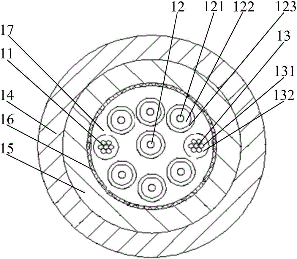
[0029] Please refer to the attached figure 1 , figure 1 It is a schematic structural diagram of the photoelectric composite cable provided by Embodiment 1 of the present invention. The photoelectric composite cable provided by Embodiment 1 of the present invention includes a fire wire cable 13, a ground wire cable 11, an optical cable 12 and at least two layers of plastic sheaths, preferably, such as figure 1 The inner plastic sheath 15 and the outer plastic sheath 14 are shown. Wherein, the inner plastic sheath 15 is coated on the cable bundle formed by the fire wire cable 13, the ground cable 11 and the optical cable 12, and the outer plastic sheath 14 is coated on the inner plastic sheath 15 , the outer plastic sheath 14 and the inner plastic sheath 15 are detachably connected, that is, the two can be peeled off.

[0030] figure 1 The middle sealing plastic sheath has two layers of inner and outer layers. In order to improve the protection performance of the cables (inc...

Embodiment 2

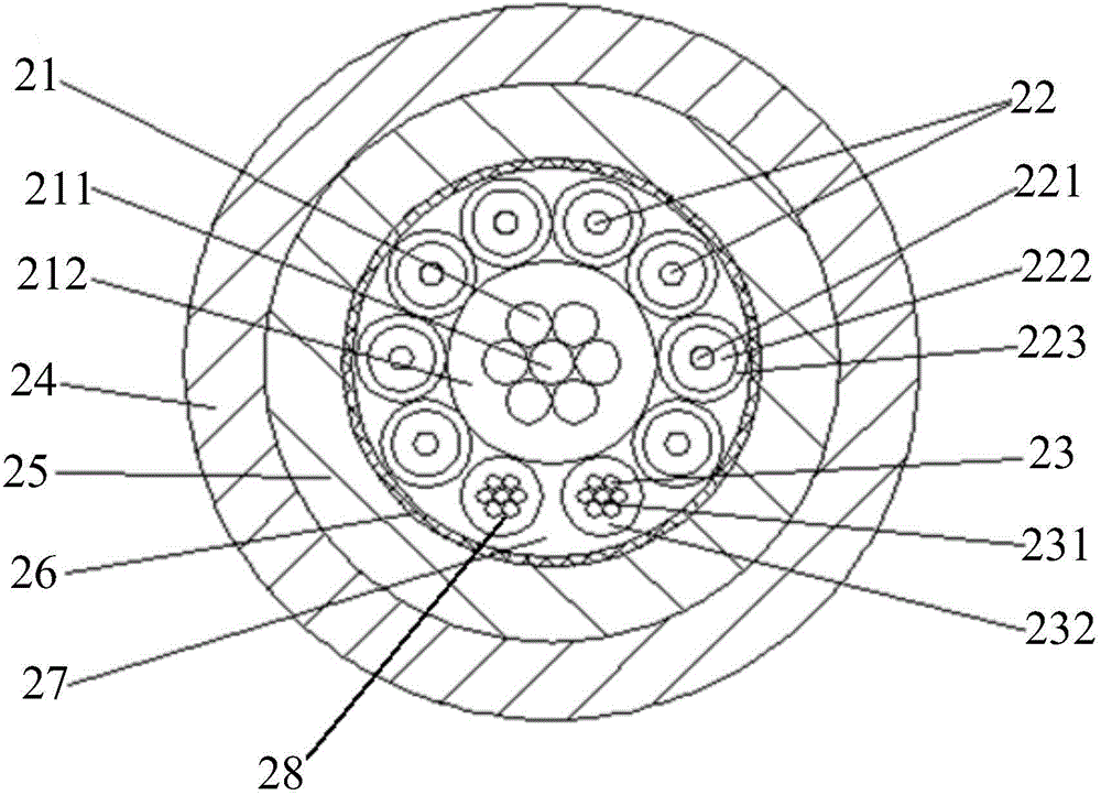
[0039] During the wiring process, the photoelectric composite cable is usually subjected to a large pulling force, which will damage the photoelectric composite cable to a certain extent. To solve this problem, please refer to the attached figure 2 , figure 2 It is a schematic structural diagram of the photoelectric composite cable provided by Embodiment 2 of the present invention.

[0040] The photoelectric composite cable provided by Embodiment 2 of the present invention includes a fire wire cable 23, a ground wire cable 28, an optical cable 22, a reinforcing rib 21 and at least two layers of plastic-molded sheaths. preferred, such as figure 2 The inner plastic sheath 25 and the outer plastic sheath 24 are shown. Wherein, the inner plastic sheath 25 is coated on the cable bundle formed by the fire wire cable 23 , the ground cable 28 and the optical cable 22 , and the outer plastic sheath 24 is coated on the inner plastic sheath 25 , the outer plastic sheath 24 and the ...

Embodiment 3

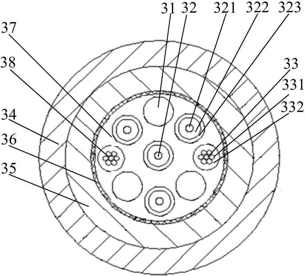
[0051] When the number of optical cables is small (such as one), the reinforcing ribs arranged in the center of the photoelectric composite cable are not enough to fill the gaps in the photoelectric composite cable, which will affect the mechanical properties of the photoelectric composite cable and easily lead to stress concentration. To solve this problem, please refer to the attached image 3 , image 3 It is a schematic structural diagram of the photoelectric composite cable provided by Embodiment 3 of the present invention.

[0052] The photoelectric composite cable provided in the third embodiment includes: a live wire cable 33 , a ground wire cable 38 , an optical cable 32 , at least two layers of plastic-molded sheaths, and a plurality of reinforcing ropes 31 located in the innermost layer of the plastic-molded sheath. preferred, such as image 3 The plastic-sealed sheath shown has two layers, the inner-layer plastic-sealed sheath 35 and the outer-layer plastic-seale...


PUM

PropertyMeasurementUnit
diameteraaaaaaaaaa

Abstract

The present invention belongs to the field of communication technology and discloses a photoelectric composite cable which comprises a live line cable, a ground line cable, an optical cable which comprises a single-core tight tube fiber and a single-core tight tube fiber sheath and a tensile reinforced layer which is arranged between the single-core tight tube fiber and the single-core tight tube fiber sheath, and at least two layers of sealed plastic sheathes which coat the cable bundle formed by the live line cable, the ground line cable and the optical cable. According to the photoelectric composite cable provided by the invention, the single-core tight tube fiber is used and is easy to cut, connect and shunt separately, at least two layers of sealed plastic sheaths are used to protect an electrical cable and the optical cable, firstly the protection performance of a multi-layer structure is good, secondly the photoelectric composite cable shape can be maintained in subsequent optical fiber connection, the reliability of photoelectric composite cable splice sealing can be improved, a fiber jumper box is not needed, and the problems of difficult wiring caused by the volume increase of a wire connection part is avoided finally.

Description

technical field [0001] The invention relates to the technical field of communication, and more specifically, relates to a photoelectric composite cable. Background technique [0002] With the rapid development of data communication technology and information technology, the network has higher and higher requirements for the performance of the integrated wiring system, and the photoelectric composite cable is more and more applied to the network wiring system. Photoelectric composite cable refers to a cable that integrates optical fiber and transmission line after adding an insulated conductor to the structure of the optical cable. The photoelectric composite cable can solve the problems of equipment power consumption and signal transmission at the same time, while retaining the characteristics of the optical cable, it can also meet the relevant requirements of the cable. [0003] The protective effect of the outer sheath of the current photoelectric composite cable is poor....

Claims


Application Information

Patent Timeline
Patent Type & Authority Applications(China)
IPC IPC(8): H01B9/00H01B7/17H01B7/18G02B6/44
Inventor 邵起明阴子阳
Owner NEW SINGULARITY INT TECHN DEV
Why Eureka
Try Eureka