Single-feed circular slit loading broadband circular polarization microstrip antenna

A technology of microstrip antenna and circular ring, applied in the field of wireless communication, can solve the problem of small bandwidth of single-feed antenna, and achieve the effect of large bandwidth, low profile and high gain

Inactive Publication Date: 2015-08-26
HARBIN INST OF TECH
View PDF9 Cites 5 Cited by
  • Summary
  • Abstract
  • Description
  • Claims
  • Application Information

AI Technical Summary

Problems solved by technology

[0006] In order to solve the problem that the existing single-feed antenna has a small bandwidth and cannot meet the actual needs, the present invention further proposes a single-feed annular slot-loaded broadband circularly polarized microstrip antenna

Method used


Image

  • Single-feed circular slit loading broadband circular polarization microstrip antenna
  • Single-feed circular slit loading broadband circular polarization microstrip antenna
  • Single-feed circular slit loading broadband circular polarization microstrip antenna

Examples


specific Embodiment approach 1

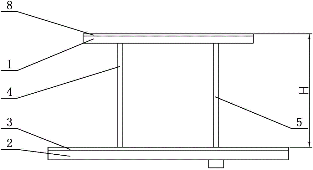
[0010] Specific implementation mode one: combine Figure 1 to Figure 3 To illustrate this embodiment, a single-feed annular slot-loaded broadband circularly polarized microstrip antenna described in this embodiment includes an upper dielectric substrate 1, a lower dielectric substrate 2, a metal floor 3, a short-circuit probe 4, and a feed probe 5. Small feed patch 6, short circuit patch 7 and radiation patch 8, the upper dielectric substrate 1 and the lower dielectric substrate 2 are arranged side by side in parallel from top to bottom, and the metal floor 3 is printed on the upper surface of the lower dielectric substrate 2 Above, the radiation patch 8 is covered on the upper surface of the upper dielectric substrate 1, the short-circuit probe 4 and the feeding probe 5 are arranged vertically side by side between the upper dielectric substrate 1 and the lower dielectric substrate 2, and the lower end of the short-circuit probe 4 Connected to the metal floor 3, the upper end ...

specific Embodiment approach 2

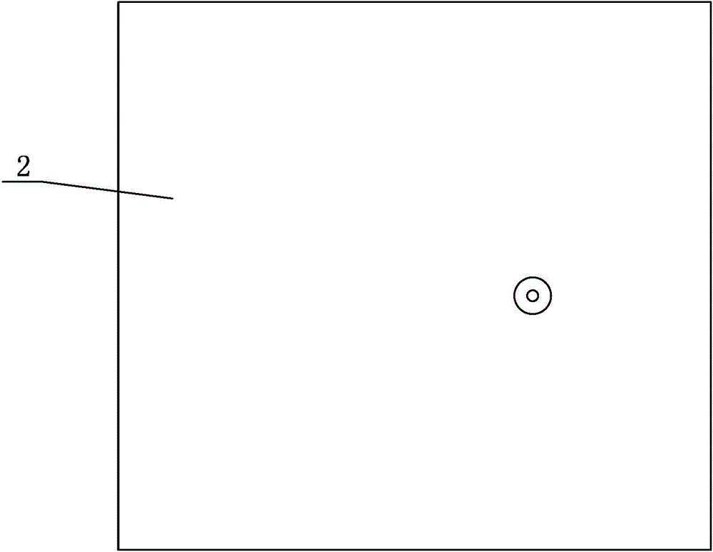
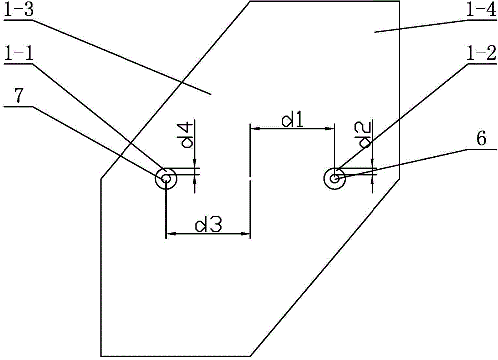
[0011] Specific implementation mode two: combination Figure 1 to Figure 3 To illustrate this embodiment, the upper dielectric substrate 1 of a single-feed annular slot-loaded broadband circularly polarized microstrip antenna described in this embodiment is composed of a rectangular plate 1-3 and two isosceles triangular plates 1-4 To form a polygonal plate, two isosceles triangular plates 1-4 are symmetrically arranged at both ends of the rectangular plate 1-3, the lower dielectric substrate 2 is a square plate with a side length of 120 mm, the upper dielectric substrate 1 and the lower dielectric substrate The distance H between 2 is 20 cm, and the thickness of the upper dielectric substrate 1 and the lower dielectric substrate 2 are both 0.254 mm. Other components and connections are the same as those in the first embodiment.

specific Embodiment approach 3

[0012] Specific implementation mode three: combination Figure 1 to Figure 3 Describe this embodiment mode, the diameter of the feed small patch 6 of a kind of single-feed annular slot loaded broadband circularly polarized microstrip antenna described in this embodiment is 1.5mm, and the circle center of the feed small patch 6 and the rectangular plate The distance d1 between the geometric centers of the bodies 1-3 is 11mm, the width d2 of the gap between the feed patch 6 and the second through hole 1-2 is 1mm, the diameter of the short-circuit patch 7 is 1.4mm, and the short-circuit The distance d3 between the center of the small patch 7 and the geometric center of the rectangular plate body 1-3 is 10 mm, and the width d4 of the gap between the short-circuit patch 7 and the first through hole 1-1 is 1.1 mm. Other compositions and connections are the same as those in Embodiment 1 or Embodiment 2.

[0013] working principle

[0014] The present invention widens the circular p...


PUM


Abstract

The invention discloses a single-feed circular slit loading broadband circular polarization microstrip antenna, relates to an antenna, and specifically relates to a single-feed circular slit loading broadband circular polarization microstrip antenna, for solving the problems in the prior art that a conventional single-feed antenna has quite small bandwidth and cannot meet realistic needs. The antenna comprises an upper-layer medium substrate, a lower-layer medium substrate, a metal floor, a short-circuit probe, a feed probe, a feed small patch, a short-circuit small patch and a radiation patch. The upper-layer medium substrate and the lower-layer medium substrate are successively arranged side by side in parallel from top to bottom, the metal floor is printed at the upper surface of the lower-layer medium substrate, the radiation patch covers the upper surface of the upper-layer medium substrate, and the short-circuit probe and the feed probe are vertically arranged side by side between the upper-layer medium substrate and the lower-layer medium substrate. The antenna provided by the invention is applied to the field of wireless communication.

Description

technical field [0001] The invention relates to an antenna, in particular to a single-feed annular slot-loaded broadband circularly polarized microstrip antenna, which belongs to the field of wireless communication. Background technique [0002] In a communication system, a device used to transmit or receive electromagnetic waves is called an antenna. The antenna can effectively convert the energy of a current or guided wave into the energy of an electromagnetic wave of the same frequency, or effectively convert the energy of an electromagnetic wave into the same frequency. Frequency of electric current or energy of guided waves. [0003] The concept of the microstrip antenna is derived from the radiation problem of the microstrip line. The structure of the microstrip line is used to develop the theory of the antenna. The prototype was first proposed in 1953, but it was not widely used in engineering at that time. During the next 20 years, there were no major breakthroughs ...

Claims


Application Information

Patent Timeline
Patent Type & Authority Applications(China)
IPC IPC(8): H01Q1/38H01Q1/50
Inventor 谷海川宗华赵志华
Owner HARBIN INST OF TECH
Why Eureka
Try Eureka