Workbench for manufacturing pressure grouting mold

A workbench and grouting technology, used in manufacturing tools, auxiliary molding equipment, ceramic molding machines, etc., can solve problems such as slurry leakage, achieve high strength and flatness, ensure flatness, and high production efficiency.

Active Publication Date: 2015-09-02
南通莱特伟特汽配科技有限公司
View PDF4 Cites 3 Cited by
  • Summary
  • Abstract
  • Description
  • Claims
  • Application Information

AI Technical Summary

Problems solved by technology

[0003] The purpose of the present invention is to: aim at the deficiencies of the prior art, provide a workbench for making pressure grouting molds, solve the problems of mold cracking, grout running, and grout leakage that are prone to occur during pressure grouting, and the strength and smoothness of the obtained gypsum abrasives. High precision, simple structure, easy operation, high production efficiency

Method used


Image

  • Workbench for manufacturing pressure grouting mold
  • Workbench for manufacturing pressure grouting mold
  • Workbench for manufacturing pressure grouting mold

Examples


Embodiment Construction

[0025] The specific embodiment of the present invention will be described in further detail below in conjunction with the drawings, wherein the same symbols in all the drawings represent the same or similar components, and the drawings in the description are in simplified form and are only for understanding the specific structure of the present invention. The following examples are only used to illustrate the technical solutions of the present invention more clearly, but not to limit the protection scope of the present invention.

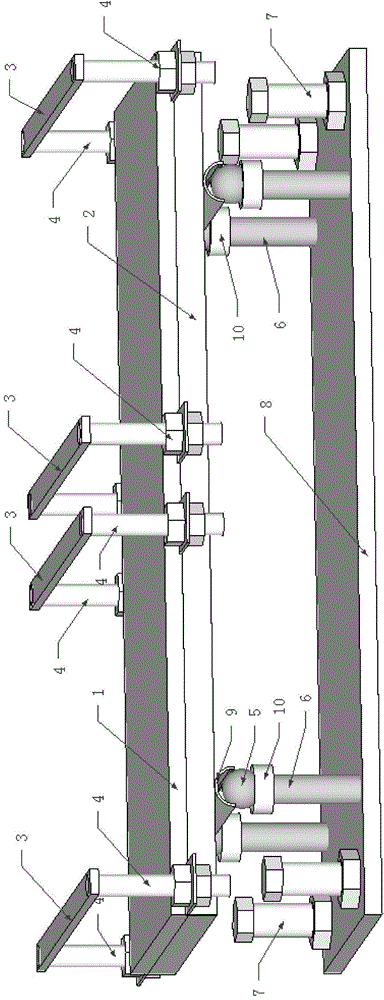
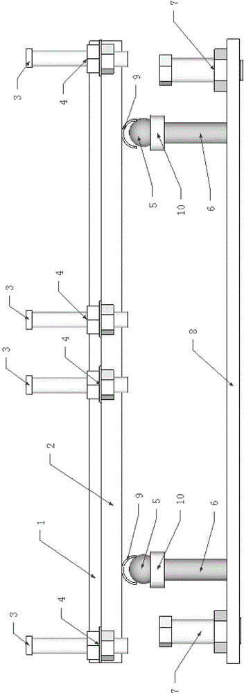
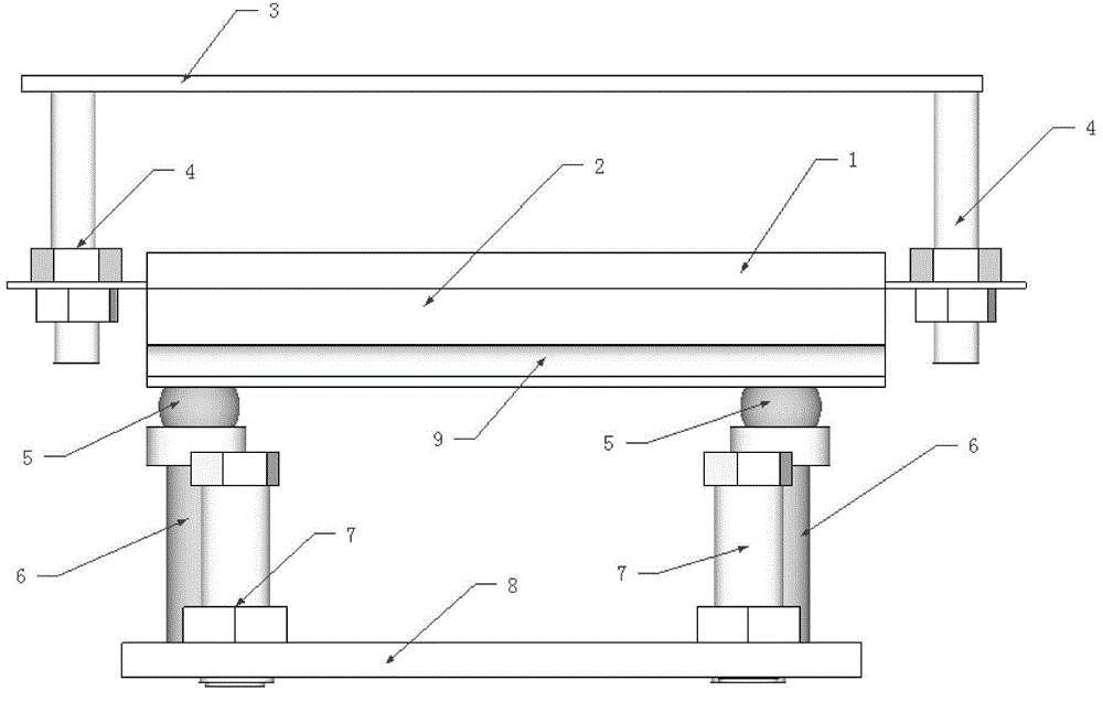
[0026] Such as figure 1 , figure 2 , image 3 Shown, a kind of workbench of making pressure grouting mould, comprises workpanel 1, frame 2 fixed on the lower surface of workpanel, is located at the lower panel 8 directly below the workpanel, horizontal frame mechanism, and described horizontal frame mechanism consists of The four horizontal frame members are divided into two groups and arranged vertically and uniformly on the working panel 1, eac...


PUM


Abstract

The invention discloses a workbench for manufacturing a pressure grouting mold, and belongs to the technical field of domestic ceramics. The workbench comprises a work face plate, a frame, a lower face plate and a horizontal frame mechanism, the frame is fixed to the lower surface of the work face plate, the lower face plate is arranged under the work face plate, the horizontal frame mechanism is divided into two groups by four horizontal frame components which are evenly distributed on the work face plate in the longitudinal direction, each horizontal frame component comprises a horizontal frame and a first adjusting bolt, and the two ends of the horizontal frames are connected with the positions, below the two sides of the work face plate, of the frame through the first adjusting bolts. Two supporting plates with sliding grooves are arranged on a longitudinal beam below the frame, supporting legs are arranged under the two ends of the sliding groove of each supporting plate, the bottom ends of the supporting legs are fixed to the lower face plate, balls are fixedly arranged at the top ends of the supporting legs, and the balls are in contact with the sliding sleeves corresponding to the top ends of the supporting legs. The phenomena of mold cracking, grout runout and the like in the pressure grouting process are avoided, the obtained plaster mold is high in strength and flatness, operation is easy and convenient, and production efficiency is high.

Description

technical field [0001] The invention relates to the technical field of daily-use ceramics, in particular to a workbench for making a pressure grouting mold. Background technique [0002] Grouting forming is one of the forming methods of daily-use ceramics production. It uses the plasticity and cohesive force of clay blanks to add water to make slurry and pour it into a plaster model with water absorption, which can be made into the shape of the inner wall of the imitation model. body. Pressure solid grouting is one of the more common forming methods for grouting. In traditional pressure solid grouting operations, multiple plaster molds are placed on the grouting table and stacked into columns. Since the solid grouting process is continuous and the injection The grout pressure is high, and it is prone to cracking, grout running, and grout leakage, etc., resulting in poor quality and large deformation of daily-use ceramic products, which affects production efficiency and econ...

Claims


Application Information

Patent Timeline
Patent Type & Authority Applications(China)
IPC IPC(8): B28B17/00
CPCB28B17/00
Inventor 李金盛
Owner 南通莱特伟特汽配科技有限公司
Why Eureka
Try Eureka